


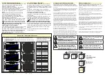

6. Meldekontakte und Kontaktbelegung
Das Überwachungsmanagement des SNT130-K erlaubt eine Vielzahl an Einstellmöglichkeiten am Gerät und kann über zwei
integrierte Relais-Kontakte fernüberwacht werden.
Relaisbelegungen
(Öffner)
:
1
: Relaismasse
1-2
: Bei
Überlast
,
Kurzschluss, Notaus
oder
Fusemode
öffnet der Kontakt
1-3
:
Überlast
oder
Übertemperatur
(
θ
>85°C)
Bei Überlast oder wenn Kerntemperatur größer als
75°C ist öffnet der Kontakt.
Das Gerät schaltet bei 85°C selbstätig die Last ab.
Kontaktbelegungen:
4
: Signalmasse (Minus)
5-4
: Standby-Modus + Reset-Funktion
5
offen
: Normalbetrieb aktivieren
6-4
: FuseMode aktivieren
6
offen
: Strombegrenzung aktivieren
7-4
: 0-10V Schnittstelle
(
x-x
: Steckbrücke/ gebrückt)
6. Signal contacts and pin assignment
The monitoring management of the SNT130-K allows a variety of settings on the device. It can be remotely monitored via two
built-in relay contacts.
Signal contacts
(Opener)
:
1
: Relayground
1-2
:
In case of Overload
,
short circuit
,
emergency stop
or
fuse mode
the contact opens.
1-3
:
Overload
or
Over-Temperature
(
θ
>85°C)
In case of overload or if core temperature exceeds
75 ° C the contact opens.
The device switches the load off at 85 °C.
Pin assignment:
4
: Signalground (minus)
5-4
: Standby-Modus + Reset-Function
5
open
: Normal operation active
6-4
: FuseMode active
6
open
: Current limiting active
7-4
: 0-10V Interface
(
x-x
: Jumper/ bridged)
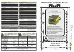
Fusemode ist aktiviert und Strombegrenzung wird überschritten
Fusemode is activated and Current-limit is exceeded
Wenn die
elektronische Strombegrenzung
aktiviert
ist (Fuse Mode), schaltet beim
Überschreiten der
eingestellten Stromgrenze
das
Gerät in Standby. Der Ausgang ist nun stromlos.
Relaiskontakt 2 ist geöffnet.
Dies geschieht auch beim Überschreiten der im
Diagramm (siehe Punkt 7) angegebenen
Überlastgrenze.
Bitte überprüfen Sie die angeschlossenen Systeme
auf Fehler.
Zum
Neustart
Verbindung zwischen
Pin 4 und Pin 6
lösen
und das Gerät durch
kurzzeitiges Schließen
der Kontakte 4-5
zurückzusetzen.
If the electronic current limitation is activated (fuse
mode), the device switches automatically to standby
when the set current limit is exceeded. The output is
now de-energized.
Relay contact 2 is open
.
This also occurs if the overload limit shown in the
diagram (see point 7) is exceeded.
Please check the connected systems for errors.
In order
to restart the device
disconnect Pins 4-6
and
reset the unit by bridging Pins 4-5 shortly
.
Wird die
elektronische Sicherung
ausgelöst (bei
Fuse-Mode),
blinken
die
LEDs Überstrom und
Ausgang rot
. Die Last wird getrennt (gelbe LED)
(siehe auch LED-Anzeigen in Punkt 4)
Is the FuseMode triggered
the
LEDs Overcurrent
and
Output
are
red
flashing
. The load is
disconnected (yellow LED)
(see also LED displays in
section 4)
Zur Anzeige der kritischen
Temperatur
leuchtet
die
LED
Temperatur gelb
.
To display the critical
temperature the LED
Temperatur glows yellow
.
Wenn im Gerät die Temperatur etwa
75°C
übersteigt,
wird der
Relaiskontakt 3 geöffnet
. Sie haben somit
die Möglichkeit, z.B. eine externe Lüftung zu
aktivieren. Das Relais bleibt solange geöffnet, bis ein
normaler Temperaturbereich erreicht wird.
If the device temperature rises above
~75°C
, the
relay 3 opens
. You have the opportunity, for
example to activate an external cooling. Relay-
contact 2 is opened, as long as the temperature is
critical.
Temperatur ist im kritischen Bereich - Temperature is in critical range
1
1
4
4
5
6
7
4
3
2
I
out
>
θ
unit
>
interne Verdrahtung
internal wiring
Relais
Relay
1 2 3 4 5 6 7
1
1
4
4
5
6
7
4
3
2
I
out
>
θ
unit
>
interne Verdrahtung
internal wiring
Relais
Relay
1 2 3 4 5 6 7
Reset
interne Relais-Belegung
internal relays assignment
SNT130-K
1
2
3
Kontakte 4-5
contacts 4-5
U
out
+
- Verbraucher
consumer
Lüfter
Fan
Relais
Relay
N
L1
interne Relais-Belegung
internal relays assignment
SNT130-K
1
2
3
Kontakt 3
contact 3
Der hier gezeigte Lüfter ist ein Vorschlag
zur Anwendung bei hohen Last- oder
Temperaturverhältnissen.
The fan shown here is a proposal for use
in high-load or temperature conditions.


