


1st edition, 12.02.2021
7000.05071, 1st edition, 12.02.2021
7000.05071
Installation
58
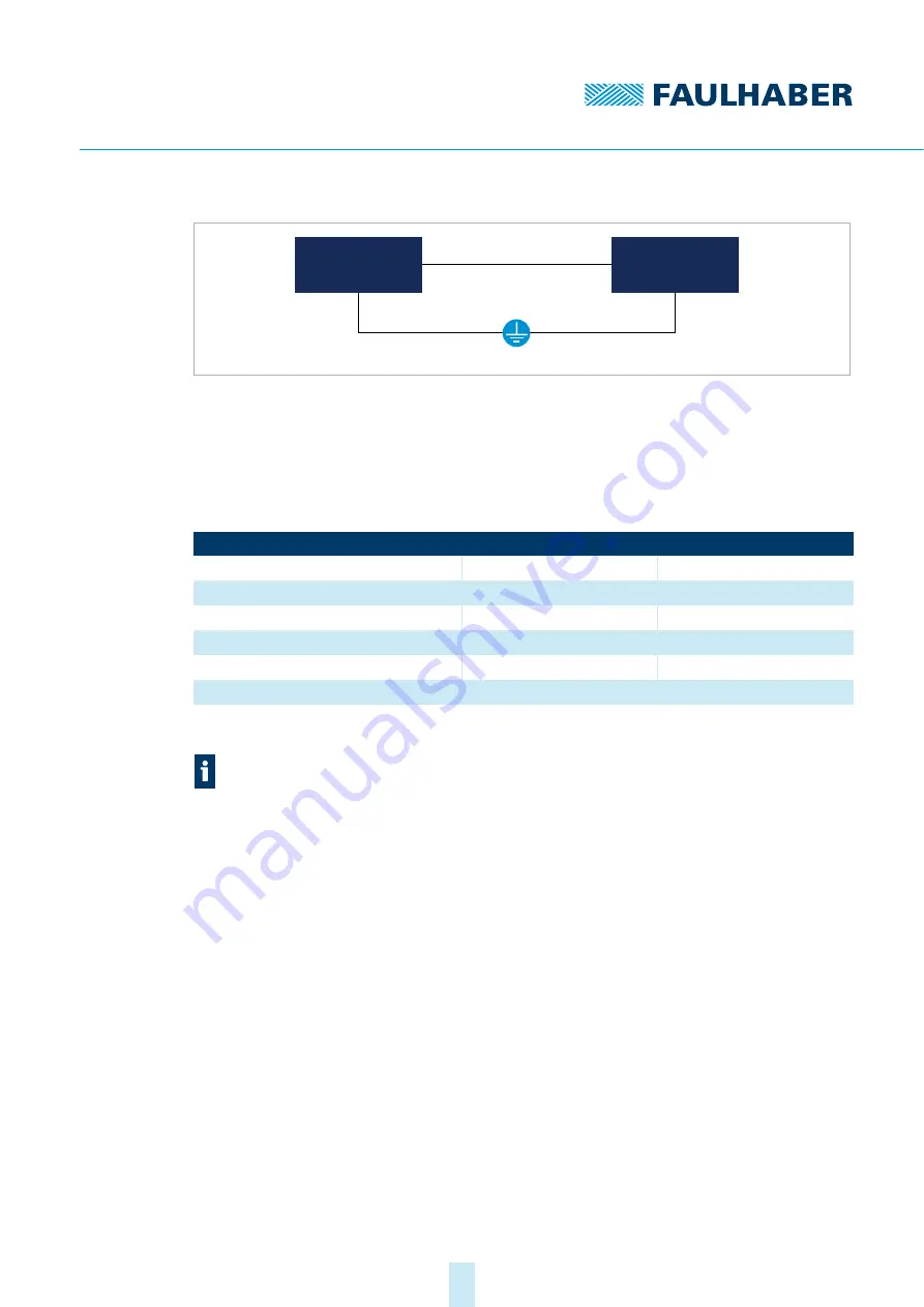
Fig. 14: Potential equalisation between electrically connected parts of the system
4.2.2
Drive connections
The maximum length of the cable between the Motion Controller and motor depends on
the sensor system used and the electrical and magnetic fields in the environment.
Tab. 87: Guide values for the cable length
Longer connection cables are generally permissible, but must be validated for the target
installation.
Optimisation of the behaviour in respect of transient emission and interference resistance
may require additional EMC measures (see chap. 4.3, p. 65)
Motion
Controller
Neutral point
Drive
Encoder type
Unshielded length
Shielded length
a)
a)
applies to cables separately shielded from the motor phase power cables.
Digital Hall sensors
0.5 m
2–5 m
Analogue Hall sensors
0.5 m
2–5 m
Incremental encoders without line driver
0.5 m
2–5 m
Incremental encoders with line driver
2 m
2–5 m
Absolute encoders without line driver
0.3 m
0.5 m
Absolute encoders with line driver
2 m
5 m
Encoders with line driver must be extended with twisted pair cables to improve the
robustness. In doing so, the cables with the respective complementary signals must be
twisted together.