1st edition, 17-09-2020
7000.05070, 1st edition, 17-09-2020
7000.05070
Installation
16
NOTICE!
Damage to mechanics
Exceeding the maximum permissible acceleration or speed while in battery mode may result
in an invalid revolution count and result in damage to the mechanics.
When designing, take into account the maximum possible acceleration of the applica-
tion.
For higher accelerations use a special configuration of the encoder.
4.2.4
Electrical circuit diagrams and external wiring
4.2.4.1
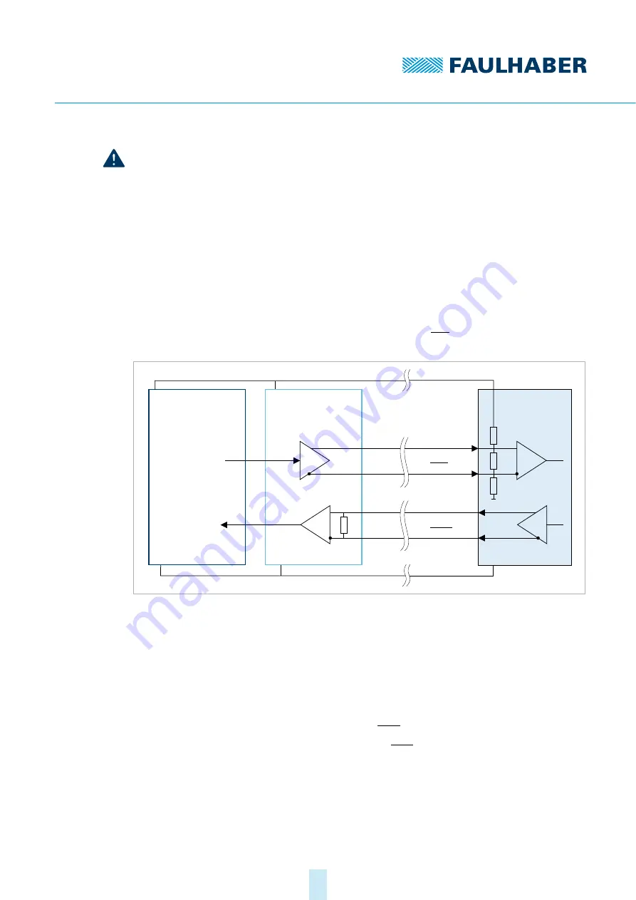
Line driver interface
The encoder has a line driver interface based on the RS422 standard. A terminating resistor
R
T
= 120
Ω
is integrated between the input signals CLK and CLK .
Fig. 6:
Electrical circuit diagram of the encoder signals and connection to a line driver
transceiver
When connecting the line driver interface on the controller side:
Use transceiver module.
The transceiver is already integrated in FAULHABER Motion Controllers of genera-
tion V3.0.
Recommended transceiver components: iC-HF, SN65LBC179, SN75179B, DS90LV019
Use a terminating resistor between data and data starting at a cable length of 1 m.
For the termination options of signals data and data see Fig. 7
Encoder
internal
U
DD
CLK
Data
GND
CLK
Data
R
T
Transceiver
U
DD
GND
R
T
Transmitter
Receiver
Controller
U
DD
GND
CLK
Data


