background image


INSTALLATION & PARTS


TORQUE SPECIFICATIONS  


Track Tank MT765 Challenger


Page 29


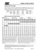
TORQUE SPECIFICATIONS


Check the tightness of ALL BOLTS, U-BOLTS, and CAP SCREWS after the first 10-15 hours of 

operation and again at end of the first week (50 hours) of operation. Tighten all bolts to torques 

specified unless otherwise noted. Check tightness of hardware periodically.


Figure 1: Common metric bolt grade markings


Metric Bolt and Screw Torque Values 


Screw


Size 


Class 4.8 


Class 8.8 or 9.8 


Class 10.9 


Class 12.9 


Lubricated

1


Dry

2


Lubricated

1


Dry

2


Lubricated

1


Dry

2


Lubricated

1


Dry

2


N-m


lb.-in.


N-m


lb.-in.


N-m


lb.-in.


N-m


lb.-in.


N-m


lb.-in.


N-m


lb.-in.


N-m


lb.-in.


N-m


lb.-in.


M6 


4.7 


42 


53 


8.9 


79 


11.3 


100 


13 


115 


16.5 


146 


15.5 


137 


19.5 


172 


N-m


lb.-ft.


N-m


lb.-ft.


N-m


lb.-ft.


N-m


lb.-ft.


M8 


11.5 


102 


14.5 


128 


22 


194 


27.5 


243 


32 


23.5 


40 


29.5


37 


27.5 


47 


35 


N-m


lb.-ft.


N-m


lb.-ft.


N-m


lb.-ft.


M10 


23 


204 


29 


21 


43 


32 


55 


40 


63 


46 


80 


59 


75 


55 


95 


70 


N-m


lb.-ft.


M12 


40 


29.5 


50 


37 


75 


55 


95 


70 


110 


80 


140 


105 


130 


95 


165 


120 


M14 


63 


46 


80 


59 


120 


88 


150 


110 


175 


130 


220 


165 


205 


150 


260 


190 


M16 


100 


74 


125 


92 


190 


140 


240 


175 


275 


200 


350 


255 


320 


235 


400 


300 


M18 


135 


100 


170 


125 


265 


195 


330 


245 


375 


275 


475 


350 


440 


325 


560 


410 


M20 


190 


140 


245 


180 


375 


275 


475 


350 


530 


390 


675 


500 


625 


460 


790 


580 


M22 


265 


195 


330 


245 


510 


375 


650 


480 


725 


535 


920 


680 


850 


625 


1080


800 


M24 


330 


245 


425 


315 


650 


480 


820 


600 


920 


680 


1150


850 


1080 


800 


1350


100 0


M27 


490 


360 


625 


460 


950 


700 


1200


885 


1350 


1000 


1700


1250


1580 


1160 


2000


147 5


M30 


660 


490 


850 


625 


1290 


950 


1630


1200


1850 


1350 


2300


1700


2140 


1580 


2700


200 0


M33 


900 


665 


1150


850 


1750 


1300 


2200


1625


2500 


1850 


3150


2325


2900 


2150 


3700


273 0


M36 


1150 


850 


1450


1075


2250 


1650 


2850


2100


3200 


2350 


4050


3000


3750 


2770 


4750


350 0


Torque values listed are for general use only, based on the 

strength of the bolt or screw. DO NOT use these values if a 

different torque value or tightening procedure is given for a 

specific application. For stainless steel fasteners or for nuts on 

U-bolts, see the tightening instructions for the specific 

application. Tighten plastic insert or crimped steel type lock 

nuts by turning the nut to the dry torque shown in the chart, 

unless different instructions are given for the specific 

application. 


Shear bolts are designed to fail under predetermined loads. Always 

replace shear bolts with identical property class. Replace fasteners 

with the same or higher property class. If higher property class 

fasteners are used, tighten these to the strength of the original. Make 

sure fastener threads are clean and that you properly start thread 

engagement. When possible, lubricate plain or zinc plated fasteners 

other than lock nuts, wheel bolts, or wheel nuts, unless different 

instructions are given for the specific application. 


1

 “Lubricated” means coated with a lubricant such as engine oil, fasteners with phosphate and oil coatings, 

or M20 and larger fasteners with JDM F13C, F13F or F13J zinc flake coating.


2

 “Dry” means plain or zinc plated without any lubrication, or M6 to M18 fasteners with JDM F13B, F13E or 

F13H zinc flake coating.


Содержание MT765 Challenger

Страница 1: ...INSTALLATION PARTS 820107 MT765 Challenger Track Tank 2023 11 08 MT765 Challenger TRACK TANK INSTALLATION and PARTS MANUAL ...

Страница 2: ...INSTALLATION PARTS 820107 MT765 Challenger Track Tank 2023 11 08 ...

Страница 3: ...essary addressed as follows Fast Ag Solutions 4130 Commerce Boulevard Windom MN 56101 This warranty shall expire one 1 year after the date of delivery of the new machinery If these conditions are fulfilled Fast Ag Solutions shall at its own cost and at its own option either repair or replace any defective parts provided that the buyer shall be responsible for all expenses incurred as a result of r...

Страница 4: ... Tanks Level ____ All Safety Signs Installed ____ Reflectors SMV and Lights Clean ____ Review Operating and ____ Safety Instructions I have thoroughly instructed the buyer on the above described equipment in which review included the Manual content equipment care adjustments safe operation and applicable warranty policy Date_____________________ Dealer s Rep Signature______________________________...

Страница 5: ...INSTALLATION PARTS MT765 Challenger Track Tank Page 5 FAST MT765 Challenger Series Tank TANK SERIAL NUMBER _______________________________ DATE PURCHASED ______________ _____ __________ ...

Страница 6: ...uded Always verify the parts and color required when ordering parts If you have any questions please contact your Fast Ag Solutions Parts and Service Department Explanation of Lists The Manual is organized as follows Table of Contents INSTALLATION PARTS TORQUE SPECIFICATIONS The parts lists are broken down into sub assemblies and listed in four 4 columns ITEM These numbers are found on the illustr...

Страница 7: ...pports 11 Install Tanks 12 Install Straps and Nylon Protector 12 Install Step Assembly 13 Install Plumbing Components 14 PARTS 15 Tanks Plumbing 15 Parts List 35500 Tanks Plumbing 20 Barrier Chain 22 Parts List 35104 JD SS Riser 22 F C SS Riser 23 Parts List 35190 JD SS Riser 23 Quick Fill 2 24 Parts List 35254 Quick Fill 2 24 Quick Fill 3 25 Parts List 35255 Quick Fill 3 25 Hardware 26 Parts List...

Страница 8: ...INSTALLATION PARTS MT765 Challenger Track Tank Page 8 ...

Страница 9: ... to the step assembly 3 Remove the step assembly 4 Remove the four bolts 2 and lower step tube 3 Discard the tube and its hardware Install Receiver Mounting Brackets WARNING Mounting bracket weighs approximately 75 lbs Use an appropriate lifting device to prevent injury 1 Install the left side mounting bracket 1 on the tractor with 3 4 x 2 GR8 bolts 2 and flange nuts Refer to the torque charts in ...

Страница 10: ...aise the receiver mounting tube 7 into position with the radar bracket to the rear and install eight center lock nuts 8 7 Tighten all eight bolts equally 1 8 1 4 so some bulge is seen on the rubber isolators Install Underside Supports WARNING Frame bracketry weighs approximately 300 lbs Use an appropriate lifting device to prevent injury 1 Install the right hand underside support 2 onto the receiv...

Страница 11: ...tall Rear Tank Supports 1 Install the right hand tank mount 1 with three M16 x 40mm GR8 8 flange bolts 2 Refer to the torque charts in this Manual for bolt torque values 2 Install the rubber isolator 3 with three 1 2 x 1 3 4 bolts 4 1 2 washers and center lock nuts Snug the bolts to slightly compress the rubber 3 Repeat the procedure for the left hand side ...

Страница 12: ...k receiver with the underside support and install ten 3 4 x 2 GR8 flange bolts 2 with flange nuts and two 1 2 x 5 1 2 bolts washers and nuts 3 Refer to torque charts in this instruction set for bolt torque values 4 Repeat the procedure with the left hand tank 4 5 Disconnect the lifting devices Install Straps and Nylon Protector 1 Position the straps 1 into place and insert its studs through the ho...

Страница 13: ... onto the tractor above the left hand tank with existing hardware 2 2 Install the base step 3 with four 5 8 x 2 GR8 flange bolts and flange nuts 4 Refer to torque charts in this instruction set for all bolt torque values 3 Attach a lifting device to the step assembly 4 Install the step assembly 5 as shown into its receiver and tighten its setscrews 6 5 Install the barrier chain between the step as...

Страница 14: ...INSTALLATION PARTS INSTALLATION Track Tank MT765 Challenger Page 14 Install Plumbing Components 1 Install all plumbing components as shown in the PARTS section s ...

Страница 15: ...INSTALLATION PARTS PARTS Track Tank MT765 Challenger Page 15 PARTS Tanks Plumbing ...

Страница 16: ...INSTALLATION PARTS PARTS Track Tank MT765 Challenger Page 16 ...

Страница 17: ...INSTALLATION PARTS PARTS Track Tank MT765 Challenger Page 17 ...

Страница 18: ...INSTALLATION PARTS PARTS Track Tank MT765 Challenger Page 18 ...

Страница 19: ...INSTALLATION PARTS PARTS Track Tank MT765 Challenger Page 19 ...

Страница 20: ...LADDER 14 35196 1 BUMPER REAR TANK 15 35197 4 WLDMNT TANK HOLDDOWN 16 35199 1 RUBBER RH TANK BUMPER 17 35236 1 PLATE LH REAR SUPPORT 18 35237 1 PLATE RH REAR SUPPORT 19 35298 1 WELDMENT CENTER SUPPORT 20 35299 1 WELDMENT CENTER SUPPORT R 21 35413 1 FENDT RADAR BRACKET DEFLECTOR 22 500009 2 VALVE 1 00 FULL PORT SINGLE UNION 23 500065 2 TEE 50 MPT X 50 HB 24 500075 1 VALVE 1 00 MANIFOLD 3 WAY BOTTOM...

Страница 21: ...TEE 1 53 530327 2 VALVE 2 00 FP MANIFOLD STUBBY 54 530354 1 ELBOW 45 2 00 MANIFOLD X 2 00 HB 55 530413 1 CROSS FITTING 1 00 56 530426 1 ELBOW 45 1 00 FLANGE X 1 00 HB 57 530445 3 FLANGE SWEEP X 1 IN HB 58 540000 16 CLAMP WORM SCREW 1 00 59 540002 11 CLAMP FP WORM SCREW 2 00 60 540012 8 HOSE CLAMP SS 1 2 12 61 540013 6 HOSE CLAMP SS 75 12 62 540014 11 HOSE CLAMP SS 1 00 16 63 540051 2 P CLAMP 2 W 3...

Страница 22: ...enger Page 22 Barrier Chain Parts List 35104 Barrier Chain ITEM PART NO QTY DESCRIPTION 1 35133 1 CHAIN STRAIGHT LINK 2 540035 2 P CLAMP 1 1 4 3 596128M 2 BOLT HH 3 8 16 X 1 GR5 MAGNI 4 596213M 2 NUT HEX 3 8 16 MAGNI 5 596250M 2 LOCKWASHER 3 8 MAGNI ...

Страница 23: ...SEALANT TO ALL THREADED CONNECTIONS BEFORE ASSEMBLY Parts List 35190 F C SS Riser ITEM PART NO QTY DESCRIPTION 1 35189 1 WLDMNT REAR TANK SS RISER 2 500014 1 CHECK VALVE 75 VITON F POLY 3 530040 1 HOSE SHANK 3 4 MPT X 3 4 HB 90 4 530131 1 NIPPLE POLY PIPE 3 4 SHORT 5 530156 1 TEE 3 4 POLY PIPE ...

Страница 24: ...CK FILL VALVE 2 10206 1 BRACKET 2 00 QUICK FILL MOUNT 3 510003 1 HOSE 2 FERTILIZER 4 530019 4 GASKET 2 00 EPDM 5 530103 2 FITTING 2 00 FP FLANGE X 2 00 HB 6 530107 1 CROSS 2 00 FULL PORT 7 530334 1 2 FP PLANGE X HOSE SHK SWEEP 8 530386 1 MANIFOLD SWEEP 2 FP FLANGE 9 540002 4 CLAMP FP WORM SCREW 2 00 10 540052 2 P CLAMP 3 W 3 8 HOLE 11 540069 2 HOSE CLAMP 2 00 T BOLT ...

Страница 25: ... 35263 1 PLATE 3 QUICK FILL MOUNT 3 510038 10 FT HOSE 3 FERTILIZER BLACK 4 530024 5 GASKET 3 EPDM 5 530111 2 MANIFOLD 3 X 2 HB 6 530297 1 Flanged Cross 3 Inch 7 530316 1 MANIFOLD REDUCER 3 X 2 CPLR 8 530439 1 MANIFOLD SWEEP FLANGE 3 9 530441 1 FLANGE SWEEP 90 X 3 HOSE BARB 10 540003 5 CLAMP WORM SCREW 3 11 540027 2 CLAMP HOSE 3 T BOLT 12 540053 2 P CLAMP 4 W 3 8 HOLE ...

Страница 26: ...INSTALLATION PARTS PARTS Track Tank MT765 Challenger Page 26 Hardware ...

Страница 27: ...INSTALLATION PARTS PARTS Track Tank MT765 Challenger Page 27 ...

Страница 28: ...ER FLAT 3 4 MAGNI 9 596260M 14 WASHER FLAT 1 2 MAGNI 10 596488M 8 BOLT HH 3 4 10 X 8 1 2 G5 MAGNI 11 596592M 2 BOLT CARRIAGE 3 8 16 X 1 MAGNI 12 596595M 8 BOLT HH M16 X 40MM GR 8 8 MAGNI 13 596603M 8 BOLT FLANGE 3 4 10 X 2 5 GR 8 MAGNI 14 596627M 8 WASHER FLAT 16MM MAGNI 15 596639M 6 BOLT HH 1 2 X 1 3 4 GR5 MAGNI 16 596742M 4 NUT TOP LOCK FLANGE 5 8 11 MAGNI 17 596769M 10 NUT HEX FLANGE 3 8 16 MAG...

Страница 29: ...0 885 1350 1000 1700 1250 1580 1160 2000 147 5 M30 660 490 850 625 1290 950 1630 1200 1850 1350 2300 1700 2140 1580 2700 200 0 M33 900 665 1150 850 1750 1300 2200 1625 2500 1850 3150 2325 2900 2150 3700 273 0 M36 1150 850 1450 1075 2250 1650 2850 2100 3200 2350 4050 3000 3750 2770 4750 350 0 Torque values listed are for general use only based on the strength of the bolt or screw DO NOT use these v...

Страница 30: ...950 700 1700 1250 2140 1580 2700 2000 3400 2500 1 1 2 990 730 1250 930 990 730 1250 930 2250 1650 2850 2100 3600 2650 4550 3350 Torque values listed are for general use only based on the strength of the bolt or screw DO NOT use these values if a different torque value or tightening procedure is given for a specific application For plastic insert or crimped steel type lock nuts for stainless steel ...

Страница 31: ...ALLATION PARTS 820107 Track Tank MT765 Challenger Page 31 Fast Ag Solutions 4130 Commerce Boulevard Windom MN 56101 1 800 772 9279 Toll Free 1 507 427 3861 Voice 1 507 427 3030 Fax https fastagsolutions com ...

Отзывы: