FarmTek Chick-Inn Скачать руководство пользователя страница 24

CHICK-INN

24

Revision date: 12.19.07

CARE AND MAINTENANCE

Proper care and maintenance of the shelter will help to 

ensure years of service. The following items identify areas 

that should be periodically checked to ensure that your 

shelter is maintained properly:
•  Regularly check the end panels and main cover to see 

that they remain tight and in proper repair.

•  Check connections and all fasteners to verify that they 

remain tight.

•  Do not climb or stand on the shelter at anytime.
•  Remove debris and objects that can accumulate on the 

shelter. Use tools that will not damage the cover when 

removing debris.

•  Remove snow to prevent excess accumulation. Use 

tools that will not damage the cover when removing 

snow.

•  Check the contents of the shelter to verify that nothing 

is touching the cover that could cause damage.

•  Check the anchoring system to ensure that all 

components are tight and in good repair.

•  If the shelter is moved, inspect all parts and 

connections before reassembling.

•  For replacement or missing parts, call 1-800-245-9881 

for assistance.


NOTE: 

With the exception of Truss Arch buildings, 

FarmTek® shelters and greenhouses 

do not

 have any 

tested loading criteria.

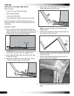
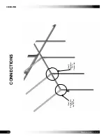
INSTALL ANTI-BILLOW ROPES (CONTINUED)

3.  Using the crank assembly, roll the side of the main 

cover to its upper-most position and secure it in place.

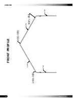
4.  Drill a 1/4" hole 

through the main cover

 above the 

rolled up portion and through the rafter leg pipe in the 

locations determined by the rope pattern.  

Dashed line shows the location of the end rafter pipe. 
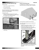
 

ATTENTION:

 All eyebolts installed at the tops of the 

rafter legs are installed through the main cover and 

above the rolled-up portion of the cover.

5.  Take one fender washer, place it on one eyebolt, insert 

the assembly through the main cover, install another 

fender washer, and insert the bolt assembly through 

the hole in the rafter leg. 


ATTENTION:

 All upper eyebolts will include a fender 

washer on 

each side of the main cover

.

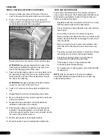
6.  Twist a 1/4" locknut onto the eyebolt and tighten the 

nut.

7.  Repeat Steps 5 and 6 for all remaining upper bolts.
8.  Move to the bottom holes, insert an eyebolt, and secure 

each with a locknut.

9.  Repeat the above procedure until all eyebolts are 

installed on both sides of the shelter.

10. With the sides rolled up, thread the rope through the 

eyebolts in the desired pattern, cut to length, tie one 

end to an eyebolt, pull the rope to remove slack, and tie 

the rope to the eyebolt to secure.

11.  Roll the side panels to their lowest position.
12. Read the shelter care and maintenance information.

Drill hole above rolled up 

portion of the cover.

Содержание Chick-Inn

Страница 1: ...te 12 19 07 Chick Inn 14 Wide Photo may show a different but similar model 2007 FarmTek All Rights Reserved Reproduction is prohibited without permission STK DIMENSIONS 103697 14 W x 12 L 103698 14 W x 18 L 103699 14 W x 24 L ...

Страница 2: ... injury and damage LOCATION Choosing the proper location is an important step before you begin to assemble the structure The following suggestions and precautions will help you determine whether your selected location is the best location Never erect the structure under power lines Identify whether underground cables and pipes are present before preparing the site or anchoring the structure Locati...

Страница 3: ...spec sheets included with the shipment To aid in the assembly read through the following definitions before you begin to assemble your shelter Conduit An assembly of pipes used to secure the main cover and end panels if equipped Purlins and some strut assemblies also consist of connected pipes to form a conduit Each pipe joint of a conduit assembly is secured with a self tapping Tek screw Coupler ...

Страница 4: ...uestions consult the Pictorial Parts Guide and all shelter diagrams for clarification or contact Customer Service NOTE At this time you do not need to open the plastic bags containing smaller parts such as fasteners or washers SQUARE THE SITE 1 Identify a corner where a building rafter will be positioned drive in a stake and string a line the exact width of the building and stake in place 2 Sting ...

Страница 5: ...lain Swaged and Plain Rafter Sections not all pieces are shown 102193 3 Way Coupler 102194 4 Way Coupler FA4472B Tek screw QH1061 Ratchet FAMF01B Fender Washer FA2059 Eyebolt QH1330 Angled Bracket 100442 Nut Setter CC6212 CC6213 Fabric Clips QH1402 Band Clamp 104074 Square to Round Tube Connect Bracket 103395 Spin Handle Plain End Panel Zippered End Panel Panel design may differ from actual panel ...

Страница 6: ...yebolts install the Tek screws at each pipe connection for additional security if desired WARNING To prevent personal injury and damage to the shelter fasten and tighten a Tek screw at each pipe and coupler joint To prevent cover damage install the Tek screw so that it does not touch the main cover or any optional side or end panels once these are installed ADDITIONAL PARTS IDENTIFICATION NOTES In...

Страница 7: ...ss for assembling the roof frame See illustration below to identify main parts of the assembly 1 Locate the required couplers and pipes and assemble the roof frame as shown below 2 Secure each pipe in the coupler using the locking eyebolt If the couplers are not equipped with locking eyebolts secure each pipe in the coupler using a Tek screw ATTENTION If used position Tek screws so they will not t...

Страница 8: ...he couplers are not equipped with locking eyebolts secure each pipe in the coupler using a Tek screw Position Tek screws so they will not touch the main cover or end panels when these are installed 3 After all legs are installed verify that all eyebolts are tight install baseboards recommended and square the frame BASEBOARDS RECOMMENDED To prevent the rafter legs from sinking into the ground baseb...

Страница 9: ...width from center of rafter leg to center of other rafter leg of the same rafter assembly Adjust if needed 3 Examine the frame and remove any sharp edges from the frame or reposition screws so they do not come in contact with the roof covers 4 Verify that the screws used to secure the purlin pipe joints are tight and positioned so they do not touch the covers NOTE These purlin joints and Tek screw...

Страница 10: ... rail 7 Position the assembly between the legs of the end rafter at the back of the shelter frame and attach it to the rafter legs using Tek screws 8 Mark the center of the end wall base rail Use this mark to center the door in the end wall 9 Locate the pedestrian door that shipped with your shelter and measure the width of the door NOTE Do not measure the channel of the door frame Before you meas...

Страница 11: ...he mark immediately below that mark on the base rail to determine the length of each vertical end wall door frame member 14 After determining the length subtract one and one half inches 1 1 2 from the dimension to account for the square to round tube connect bracket 104074 that will be attached to the top of each tube in a later step ATTENTION See the diagram in Step 16 for clarification if needed...

Страница 12: ...squeeze the clamp back into shape once it is positioned on the rafter 19 Verify that the angled bracket QH1330 attached to the lower end of each vertical frame tube is positioned to the outside of the door frame rough opening 20 Carefully position one 1 vertical door frame tube on the base rail and align the inside edge with one mark of the rough door opening Install Tek screws Rough door opening ...

Страница 13: ...ertical frame tubes 30 Verify that the vertical door frame tubes are plumb and tighten the band clamps 31 Recheck the rough door opening dimensions top and bottom to verify that the door opening is square 32 Return to each band clamp and install a Tek screw through the clamp and into the rafter pipe from the inside of the shelter to secure the clamp to the rafter View above shows the inside or bac...

Страница 14: ...e end wall and center the panel between the rafter legs of the front non door end wall 4 Cut the panel pocket as shown below Use the dashed lines below and in the previous diagram as guides NOTE The short section of pocket outlined above is the only pocket that the square base rail will be inserted into 5 After trimming the panel pocket at each end previous photo take the square tube base rail cut...

Страница 15: ... NOTE Previous diagram shows the panel as seen from the outside Allow a few inches of the pipe to extend outside of the end panel pocket at the end where you will position and attach the roll up crank assembly 11 With the roll up conduit positioned in the end panel pocket secure the conduit in place using eight 8 CC6212 fabric clips for 1 315 pipe and Tek screws Roll Up Conduit NOTE Evenly space t...

Страница 16: ...the panel edge under the base rail of the end wall frame and fold it up onto the top surface of the base rail on the inside of the frame Base Rail of End Wall Inside of end panel Tek screw and fender washer ATTENTION If the base rail is on a perimeter frame such as treated wood boards as recommended insert and pull the end panel material between the treated board and the base rail The end panel ca...

Страница 17: ...t for an installation of wire mesh optional purchase not included If you have purchased and installed wire mesh you may need to alter the following steps to account for that installation 1 Use a utility knife to cut the end panel as shown below The dashed lines show where to make three 3 diagonal cuts 2 After cutting the end panel in the locations shown by the diagonal dashed lines remove the part...

Страница 18: ...ws in the previous diagram show which surface of the vertical tube to attach the end panel material that is wrapped around the vertical door frame tube 3 With the end panel secured to the left door frame tube detach the header tube from the frame member on the right Allow the brackets to remain attached to the header View is from the outside of the frame End panel is not shown to better show the f...

Страница 19: ... of the door before you secure it to the end frame Shim if needed Each ratchet is attached through the end panel using a Tek screw Ratchet height will be lower than the height of the sidewall when sidewall is rolled up to its highest position See cover photo of these instructions Complete these steps to attach the ratchets to the frame 1 Locate the four ratchets and the required Tek screws used to...

Страница 20: ...e cover toward the base of the frame Rope may not be needed for small shelters 7 Toss the ropes over the frame and pull the cover into position One person is required at each rope NOTE Do not use the straps in the bonnet pocket of the main cover to pull the cover into place These straps will pull out 8 With the cover on the frame center the cover end to end and side to side as needed Ropes NOTE Th...

Страница 21: ...sitioned as desired and tighten the ratchets NOTE If the strap length is too long and binds in the ratchet loosen the ratchet shorten the strap and retighten the ratchet as needed 15 After tightening the ends of the main cover take half of the CC6213 fabric clips that remain from the earlier procedure and Tek screws and move to the inside of the shelter See chart on Page 14 Step 1 if needed 16 Usi...

Страница 22: ...TION A few inches of the conduit should extend beyond the edge of the cover See diagram above 2 Evenly space the fabric clips to secure the main cover to the cover conduit 3 Attach the universal joint to the conduit in the pocket using a Tek screw to secure the connection 4 Secure one 1 49 5 plain pipe to the remaining end of the universal joint using a Tek screw NOTE This extension pipe can be tr...

Страница 23: ...s are installed to keep the side roll up portion of the main cover in place when it is rolled down The following steps describe one way to install the anti billow rope system 1 Locate the 1 4 eyebolts 1 4 locknuts and fender washers that shipped with the shelter 2 Using the above diagram as an example drill a 1 4 hole through the rafter legs at the bottom in the locations determined by the rope pa...

Страница 24: ...OPES CONTINUED 3 Using the crank assembly roll the side of the main cover to its upper most position and secure it in place 4 Drill a 1 4 hole through the main cover above the rolled up portion and through the rafter leg pipe in the locations determined by the rope pattern Dashed line shows the location of the end rafter pipe ATTENTION All eyebolts installed at the tops of the rafter legs are inst...

Страница 25: ...25 CHICK INN Revision date 12 19 07 QUICK START GUIDE 14 Wide Chick Inn Endwall 14 6 1 4 Height Width 5 0 9 4 9 16 Height Grid Represents 12 Squares FRONT Frame length shown may differ from actual frame ...

Страница 26: ...CHICK INN 26 Revision date 12 19 07 FRONT PROFILE End Rafter 102193 Mid Rafter 102194 End Rafter 102193 Mid Rafter 102194 End Rafter 102193 Mid Rafter 102194 166P060 166P060 166P096 166P096 ...

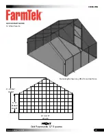
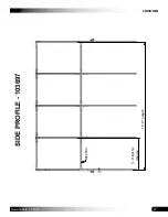
Страница 27: ...27 CHICK INN Revision date 12 19 07 SIDE PROFILE 103697 166P034 Rafter Spacing 3 0 12 0 Length ...

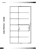
Страница 28: ...CHICK INN 28 Revision date 12 19 07 SIDE PROFILE 103698 166P034 Rafter Spacing 3 0 18 0 Length ...

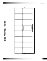
Страница 29: ...29 CHICK INN Revision date 12 19 07 SIDE PROFILE 103699 166P034 3 0 Rafter Spacing 24 0 Length ...

Страница 30: ...CHICK INN 30 Revision date 12 19 07 CONNECTIONS End Rafter Purlin Connection View 1 Mid Rafter Purlin Connection View 2 ...

Страница 31: ...31 CHICK INN Revision date 12 19 07 CONNECTION DETAILS 102193 3 Way Coupler Purlin Rafter Purlin 102194 4 Way Coupler Rafter View 1 End Rafter Purlin Connection View 2 Mid Rafter Purlin Connection ...

Страница 32: ...CHICK INN 32 Revision date 12 19 07 END FRAMING DOOR END Top Rafter End Wall Connection View 1 Rafter End Wall Connection View 2 Door style shown may differ from actual door ...

Страница 33: ... Bracket End Wall Sq Tubing Rafter View 1 Top Rafter End Wall Connection View 2 Rafter End Wall Connection QH1402 1 66 Band Clamp Rafter End Wall Sq Tubing 104074 Sq Rnd Tubing Connection NOTE View 1 shows the connection detail as seen from the back or from inside the shelter ...

Страница 34: ...TAILS QH1330 90 Bracket QH1330 QH1330 QH1330 QH1330 QH1402 1 66 Band Clamp 104706 Green House Door w Lock 2 102897 Cut Second to Fit 102897 Cut to Fit 102897 Cut to Fit 104074 Sq Rnd Tube Connection QH1330 Door style shown may differ from actual door ...

Страница 35: ...ied Baseboard NOTES Pedestrian door is centered in the end wall End wall base rail consists of one 1 50 x 1 50 square tube cut to length Measure the pedestrian door and frame the rough opening approximately 1 2 wider and higher than the actual door End Wall Diagram 14 Wide with a Pedestrian Door Frame shown may differ slightly from actual frame ...

Отзывы: