Assembly - 500, 600, 660
24
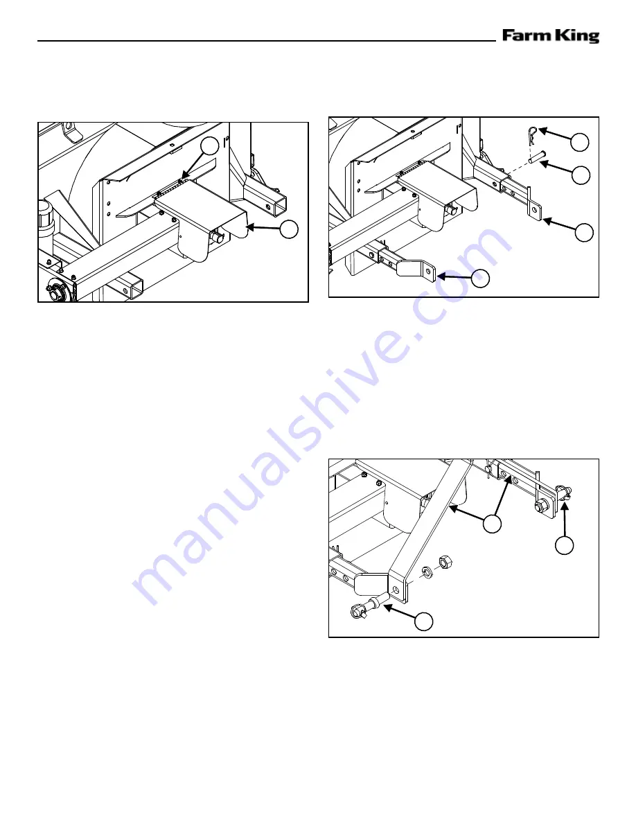
Hitch Assembly
Figure 6
Align the right and left hitch tubes (Item 1)
with the welded sleeves on the main body.
Slide the tubes into the sleeves as shown, with the
end brackets facing in. Each tube has four mounting
holes, to be used depending on the tractor.
Attach each tube using one 3/4” x 3-1/4” pin (Item
2)
.
Figure 7
Align the left and right hitch arms (Item 1)
with the outside of the end brackets on the
hitch tubes.
Attach each hitch arm with a Category 1 lift arm pin
(Item 2)
, washer, and nut
The linch pin / lift arm pin should face out. Do not
tighten any hardware until assembly is complete.
1
2
3
1
2
2
1
PTO Shield
Figure 5
Bolt the PTO shield (Item 1)
to the top of
the gearbox assembly using two 1/4” x 3/4” hex
bolts (Item 2)
lock washers. .
Hook one end of the spring in the hole in the back
edge of the PTO shield and the other end of the
spring in the hole punched in the edge of the
gearbox assembly.
1
2
Содержание 500
Страница 1: ...032016 FK311 OPERATOR AND PARTS MANUAL Snowblower Model 500 600 660 ...
Страница 2: ......
Страница 6: ...Warranty Registration Form 500 600 660 4 ...
Страница 8: ...Introduction 500 600 660 6 ...
Страница 12: ...Introduction 500 600 660 10 ...
Страница 14: ...Safety 500 600 660 12 ...
Страница 24: ...Assembly 500 600 660 22 ...
Страница 30: ...Assembly 500 600 660 28 ...
Страница 32: ...Operation 500 600 660 30 ...
Страница 44: ...Operation 500 600 660 42 ...
Страница 46: ...Maintenance 500 600 660 44 ...
Страница 52: ...Maintenance 500 600 660 50 ...
Страница 54: ...Parts Identification 500 600 660 52 ...
Страница 66: ...Specifications And Shipping Kit Numbers 500 600 660 64 ...
Страница 68: ...Specifications And Shipping Kit Numbers 500 600 660 66 HardwareTorque Values Metric Chart ...
Страница 69: ...Specifications And Shipping Kit Numbers 500 600 660 67 Imperial Chart ...
Страница 70: ...Specifications And Shipping Kit Numbers 500 600 660 68 ...
Страница 72: ...Warranty 500 600 660 70 ...
Страница 75: ......


