FAR KJ 46 Скачать руководство пользователя страница 34

34

75036155 - KJ46 - rev 00 - ( 06-2022 )

KJ 46

f18

f17

GB

F

I

I

D

Y


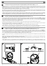
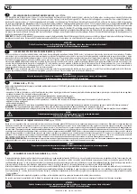
RABBOCCO OLIO NEL CIRCUITO OLEODINAMICO 

(fig. 

f17-f18

)

Il rabbocco dell’olio del circuito oleodinamico si rende necessario dopo un lungo periodo di lavoro (15000 cicli),o quando si avverte un calo di corsa della rivettatrice. Procedere quindi 

come segue: con rivettatrice non alimentata accertarsi che la corsa sia regolata sul valore massimo: tacca sulla ghiera di regolazione completamente in posizione avanti, altrimenti 

ruotare la ghiera  (

S

) nel senso indicato dal segno “+” sino al finecorsa. Posizionare la macchina in verticale, rimuovere il tappo (

I

) servendosi della chiave a brugola di 

mm 4

 (in 

dotazione). Durante questa operazione prestare la massima attenzione per evitare fuoriuscite di olio. Avvitare nella sede del tappo (

I

) il contenitore olio (

Y

) (in dotazione) preventivamente 

riempito con olio idraulico di 

HLP 32 cSt 

. Mantenendo la rivettatrice verticale, attivare l’alimentazione dell’aria, premere il pulsante (

D

) facendo compiere alla rivettatrice una serie di 

cicli fino a quando non sia completamente cessata l’emissione di bolle d’aria all’interno del contenitore (

Y

), questa condizione sta a significare che il rabbocco dell’olio è completato. A 

questo punto disattivare l’alimentazione dell’aria e, con rivettarice sempre verticale, svitare il contenitore olio (

Y

) e richiuderlo. Procedere quindi alla chiusura del tappo (

I

) verificando 

l’integrità della rondella ermetica e ripetere tutte le regolazioni per la posa in opera dell’inserto riportate nel capitolo "Uso della rivettatrice"

CAUTELA:

 È di estrema importanza attenersi alle istruzioni sopra indicate ed effettuare le operazioni di rabbocco olio muniti di guanti. Nel caso di svuotamento completo del circuito 

idraulico, recuperare tutto l’olio in un apposito contenitore e avvalersi successivamente di una ditta autorizzata allo smaltimento dei rifiuti.

ATTENZIONE!

Prima di scollegare il tubo dell’aria compressa dalla rivettatrice accertarsi che quest’ultimo non sia in pressione! Si raccomanda l’uso di olio HLP 32 cSt o simili.


TOPPING UP THE OIL-DYNAMIC CIRCUIT 

(fig.  

f17-f18

)

The oil-dynamic circuit should be topped up after a long period of work (15000 cycles), or when there is a power loss of the riveting tool. When the riveting tool is not 

powered, make sure that the stroke is set to the maximum value: notch on the adjustment ring nut fully forward, otherwise turn the ring nut (

S

) in the direction indicated by 

the "

+

" sign up to the end stop.  Put the riveting tool (not fed) in a vertical position and remove the plug (

I

) by means of a 

4 mm

 Allen wrench (equipped). During this operation 

check the oil level in order to avoid any overflowing. Then pour the oil 

HLP 32 cSt

 into the oil container (

Y

) (equipped) which shall be screwed to its seat on the plug (

I

).

While keeping the riveting tool in vertical position and starting air feeding, push the button (

D

) and make the riveting tool carry out some cycles until air bubbles inside the 

container stop coming out. This condition indicates that the topping up of the oil has been fully achieved. At this point stop the air feeding and while keeping the riveting 

tool in a vertical position, unscrew and close the oil container (

Y

) and the plug (

I

) checking the soundness of the hermetic washer and repeat all the adjustments for placing 

the insert as indicated in the chapter "Using the riveting tool".

ATTENTION:

 It is very important to follow the above-mentioned instructions and use gloves during oil topping up.

If you need to empty completely the hydraulic circuit, you must put the oil in a suitable container and contact a company authorized to dispose of wastes.

ATTENTION!

Before disconnecting the compressed air hose, make sure that it is not under pressure! We recommend to use oil HLP 32 cSt or similars.

ATTENTION!

Avant de débrancher le tuyau d’air comprimé de la riveteuse, s’assurer qu’il n’est plus sous pression!  Nous recommandons l'utilisation d'huile HLP 32 cSt ou similaires.


REMPLISSAGE DE L’HUILE DU CIRCUIT HYDRAULIQUE


(fig.  

f17-f18

)

Le remplissage de l’huile du circuit hydraulique est nécessaire après une longue période de travail (15000 cycles), ou en cas de diminution de la course de la riveteuse. 

Procéder comme suit: sur la riveteuse non alimentée vérifier que la course est réglée sur la valeur minimale : encoche sur la bague de réglage complètement en avant, 

sinon tourner la bague (

S

) dans le sens indiqué par le signe « 

+

 » jusqu’au fin de course.  Positionner la machine à la verticale, retirer le bouchon (

I

) à l’aide d’une clé Allen 

de 

4 mm

 (fournie). Durant cette opération, faire très attention pour éviter le renversement d’huile. Visser le récipient d’huile (

Y

) (fourni) préalablement rempli d’huile 

hydraulique 

HLP 32 cSt 

 sur le bouchon (

I

). Tout en maintenant la riveteuse à la verticale, activer l’alimentation d’air, appuyer sur le bouton (

D

) en faisant effectuer quelques 

cycles à la riveteuse, jusqu’à ce qu’ait cessé le dégagement de bulles d’air dans le réservoir (

Y

), cette condition indique que le ravitaillement de l’huile est terminé. Ensuite, 

couper l’alimentation d’air et, toujours avec la riveteuse à la verticale, dévisser le récipient d’huile (

Y

) et le refermer. Procéder ensuite à la remise en place du bouchon (

I

en contrôlant l’état de la rondelle hermétique et effectuer tous les réglages de pose de l’insert chapitre « Utilisation de la riveteuse ».

RECOMMANDATION:

 Il est très important de veiller au respect des instructions ci-dessus et d’effectuer le ravitaillement d’huile muni de gants. En cas de vidange complète 

du circuit hydraulique, récupérer l’huile dans un récipient et la remettre à un centre agréé de collecte des déchets.
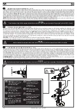
IMPORTANTE:

 Assicurarsi che il 

tappo di rabbocco olio ( 

) venga 

serrato con una coppia pari a: 

min. 5 Nm ÷ Max. 8 Nm.

ATTENTION:

 Make sure that the 

oil filler cap ( 

) is tightened at a 

torque corresponding to 

min. 5 Nm ÷ Max. 8 Nm.

IMPORTANT: 

S’assurer que le 

bouchon de remplissage d’huile 

( I )

 soit vissé avec couple de 

min. 

5 Nm ÷ Max. 8 Nm

.

WICHTIG:


Es muß sichergestellt 

werden, daß der Öltankverschluß 

( I )

 mit einem 

min. 5 Nm ÷ Max. 

8

 Nm liegenden Anzugsmoment 

angeschraubt wird.

IMPORTANTE:

 Asegurarse que 

el tapón de llenado aceite ( 

) sea 

enroscado con un par de acople 

correspondiente a: 

mín. 5 Nm ÷ Máx. 8 Nm

.

UWAGA!

 Upewnić się że korek wlewu 

oleju 

)

 został dokręcony z siłą równą 

min. 5 NM - Maks. 8 NM

.

ВНИМАНИЕ!

Убедиться в том, что пробка масляного бака 

)

 завинчивается с усилием затяжки от 

мин.


5 Нм до макс. 8 Нм

IMPORTANTE:

 Certificar-se que a 

tampa de reabastecimento de óleo 

) seja apertada com um binário 

igual a: 

mín. 5 Nm

 ÷ 

Máx. 8 Nm

.

D

F

GB

I

E

PL

RUS

PT

T

S

-

+

Содержание KJ 46

Страница 1: ...D EMPLOI PIECES DETACHEES BERSETZUNG VON ORIGINALANLEITUNGEN PNEUMATISCH HYDRAULISCHES NIETWERKZEUG F R BLINDNIETMUTTERN M4 M10 BEDIENUNGSANLEITUNG ERSATZTEILE TRADUCCION DE LAS ISTRUCCIONES ORIGINAL...

Страница 2: ...P THE OIL DYNAMIC CIRCUIT 34 MAINTENANCE 36 DISPOSAL OF THE RIVETING TOOL 36 TROUBLE SHOOTING 39 SPARE PARTS 48 D CLARATION DE CONFORMIT 4 GARANTIE 5 INSTRUCTIONS ET MESURES DE SECURITE 6 IDENTIFICATI...

Страница 3: ...POWIETRZEM 19 WST PNE CZYNNO CI PRZED URUCHOMIENIEM 21 REgULACjAZESPO UTRZPIE g OWICA 21 U YTKOWANIE NITOWNICY 23 REgULACjA SI Y ZACI gANIA ZA POMOC REgULATORA CI NIENIA I MANOMETRU 25 MECHANICZNA REg...

Страница 4: ...er Berechtigte zur Bildung der technische Brosch re ist Massimo Generali bei der Firma Far S r l mit Sitz in Via giovanni XXIII 2 Fraz Quarto Inferiore 40057 granarolo Emilia Bologna Italy La firmatar...

Страница 5: ...ertragsh ndlererworbenund ausschlie lichzudenZweckenverwendet wird f r die es konzipiert wurde Die Garantie wird ung ltig wenn das Ger t nicht in Einklang mit den Anweisungen in der Betriebs und Wartu...

Страница 6: ...en Die Firma FAR s r l haftet nicht f r durch defekte Teile verursachte Sch den sofern diese auf die Mi achtung der o g Vorschrift zur ckzuf hrensind Richtlinie85 374 EWG DieListederReparaturservicesi...

Страница 7: ...ci zamiennych firma FAR nie ponosi adnej odpowiedzialno ci za wypadki powsta e na skutek niew a ciwego u ycia narz dzia Dyrektywa UE 85 374 Lista punkt w serwisowych jest dost pna na naszej stronie i...

Страница 8: ...orrect size to be used Do not carry the connected tool by pulling the hose The hole must be far from any heating sources or from cutting parts Keep the tools in good conditions do not remove either sa...

Страница 9: ...ss o ponderada A seja superior ao limite de seguran a de 70 dB A usar adequados equipamentos de prote o individual do ouvido tamp es diminui o do tempo de exposi o di ria etc Manter a bancada e ou a r...

Страница 10: ...VETER L outil de pose KJ 46 est identifi par un marquage indiquant raison sociale et adresse du fabricant d signation de l outil de pose marquage CE En cas de recours au service apr s vente il faut to...

Страница 11: ...maszyny i oznakowaniem CE Korzystaj c z pomocy technicznej nale y zawsze poda dane znajduj ce si na oznaczeniu KJ 46 CE Ragione sociale e indirizzo del fabbricante Company name and address Raison soc...

Страница 12: ...dimensions et le poids du pistolet en la rendant tr s maniable Les risques de fuites du syst me ol odynamique sont limin s par l utilisation de joints haute r sistance ALLGEMEINES UND ANWENDUNGSBEREIC...

Страница 13: ...nacznie zmniejszy y ci ar narz dzia i polepszy y jego ergonomi Ponadto udoskonalony system uszczelniaczy eliminuje mo liwo spadku mocy zacisku M4 M10 1 2 KJ46 KJ 46 A ferramenta destina se apenas a se...

Страница 14: ...Manometro X Dado bloccaggio regolatore di pressione A Threaded tie rod B Head C Ring nut clamping head D Control push button E Compressed air connection F Pressure control valve G Protection bottom H...

Страница 15: ...de tope U Protecci n V Man metro X Tuerca de bloqueo del regulador de presi n A Tirante roscado B Cabe a C Virola de bloqueio da cabe a D Bot o de comando E Conex o do ar comprimido F V lvula de contr...

Страница 16: ...2 5 m s2 A weighted emission sound pressure level 74 dBA Peak C weighted instantaneous sound pressure 130 dBC A Weighted sound power 86 dBA DONN ES TECHNIQUES Pression d utilization 6 7 BAR Diam tre...

Страница 17: ...Nl nl litry przy 20 C ci nienie atmosferyczne Si a maksymalna 6 BAR 24000 N Skok 7 mm Waga 2 540 Kg Temperatura robocza 5 st C 50 St C Przyspieszenie r ka rami 2 5 m s2 Ci nienie akustyczne emisji sk...

Страница 18: ...er of the air entry valve Q to feed the tool AIR FEED fig f1 The compressed air system must be provided with air cleaners and condensation drains and must guarantee that the air supplied to the feeder...

Страница 19: ...muss man kontrollieren dass der Druckluftversorgung der Nietmaschine dem unter technischen Daten auf Seite 16 dieser Anleitung angegebenen Druckwert entspricht Um das Werkzeug zu speisen den Steuerkol...

Страница 20: ...assembled on this riveting tool corresponds to a M8 thread Before using the riveting tool and after each change of format the stroke power must be adjusted according to the size type of insert and th...

Страница 21: ...illar una tuerca remachable de la longitud querida sobre el tirante fileteado manualmente hasta que la cabeza de la tuerca toque la cabeza B de la remachadora La cabeza es ajustada correctamente si el...

Страница 22: ...aded inserts by choosing between two different methods of use 1 Power setting via pressure regulator and pressure gauge on the bottom of the riveting tool 2 Mechanical stroke adjustment via adjustment...

Страница 23: ...aplicaci n de remaches mediante el ajuste de potencia antes de utilizarla consulte el cap tulo titulado AJUSTE DE LA POTENCIA A TRAV S DE UN REGULADOR DE PRESI N Y UN MAN METRO ATEN O N o absolutament...

Страница 24: ...use fonctionne mais elle incapable d effectuer la course et de serrer l insert En augmentant progressivement la puissance via le r gulateur de pression M la d formation de l insert est progressivement...

Страница 25: ...les y campo de aplicaci n de la m quina no bajar del ajuste m nimo le do en el man metro V suministrado en la parte inferior de 1 bar y no superar el ajuste m ximo de 5 5 bar Sigue REGULA O DA POT NCI...

Страница 26: ...vel talonnage de la pression Le manom tre situ dans le fond n est qu un instrument indicatif de lecture de la pression et ne doit pas remplacer lors du r glage talonnage de la machine la v rification...

Страница 27: ...s de 0 5 bar colocando el puntero rojo de referencia en el centro de los espacios entre una muesca y la siguiente REGULA O DA POT NCIA PELO REGULADOR DE PRESS O E MAN METRO DEFINI ES DE F BRICA fig f7...

Страница 28: ...ourse S dans le sens indiqu par le symbole Dans cette condition l index de but e T grav sur la bague sera positionn juste au del du milieu de la fente sur le manchon c t moteur R installer la t te B e...

Страница 29: ...ci n de apriete Una vez realizados los ajustes desconecte el suministro de aire comprimido y vuelva a colocar la protecci n U para evitar cambios accidentales en el ajuste MECHANICZNA REGULACJA SKOKU...

Страница 30: ...is completely pulled and push the button P to release the tie rod fig f11 Insufficient deformation fig f12 1 the insert could rotate inside the housing compromising its use and resistance Excessive d...

Страница 31: ...ownic do pracy reguluj c si zaci gania lub reguluj c mechanicznie skok roboczy jak pokazano na stronach 24 29 Na gwintowany trzpie A nak adamy nitonakr tk pod wp ywem lekkiego nacisku trzpie wkr ci si...

Страница 32: ...upling release plug R is in phase with the slot on the sleeve Make the pin supplied pass through the pertinent service hole and apply a light pressure on the head inwards in order to dechuck the tie r...

Страница 33: ...a virola que se afloj anteriormente ACHTUNG Die obenstehenden schritte sind bei nicht gespeister maschine durchzuf hren ATENCI N Las operaciones susodichas tienen que ser efectuadas con la m quina par...

Страница 34: ...riveting tool in a vertical position unscrew and close the oil container Y and the plug I checking the soundness of the hermetic washer and repeat all the adjustments for placing the insert as indica...

Страница 35: ...NG Stellen Sie vor dem Trennen des Druckluftrohres der Nietmaschine sicher dass dieses nicht unter Druck steht Es empfiehlt sich l HLP 32 cSt oder hnliches zu verwenden LLENADO DE ACEITE DEL CIRCUITO...

Страница 36: ...luminium plastic material etc Then proceed to scrap the materials in accordance with current laws ENTRETIEN Entretien quotidien s assurer que le tirant filet n est pas endommag contr ler le syst me d...

Страница 37: ...przewod w powietrza upewni si ze ci nienie zasilaj ce nie przekracza 7 bar Konserwacja tygodniowa sprawdzamy poziom oleju rys f18 Przegl d serwisowy Zalecamy gruntowny przegl d narz dzia po 300 000 cy...

Страница 38: ...o del regolatore di pressione Rivolgersi al centro assistenza Danneggiamento Valvola di scarico rapido Rivolgersi al centro assistenza Danneggiamento guarnizione manometro Rivolgersi al centro assiste...

Страница 39: ...essure regulator damage malfunctioning Contact the service center Quick exhaust Valve Damage Contact the service center Pressure gauge damage Rivolgersi al centro assistenza Thepr essureg augedo es no...

Страница 40: ...onnement du r gulateur de pression Contacter le service apr s vente SAV Dommage Soupape d chappement rapide Contacter le service apr s vente SAV Dommage au joint du manom tre Contacter le service apr...

Страница 41: ...des Druckreglers Wenden Sie sich an das Service Center Besch digung Schnellauslassventil Wenden Sie sich an das Service Center Besch digung der Dichtung des Manometers Wenden Sie sich an das Service C...

Страница 42: ...en contacto con el servicio tecnico Da o de la v lvula de descarga r pida P ngase en contacto con el servicio tecnico Da os en la junta del man metro P ngase en contacto con el servicio tecnico E lma...

Страница 43: ...regulatora ci nienia Skontaktowa si z centrum obs ugi klienta Uszkodzenie zaworu szybkiego spustu Skontaktowa si z centrum obs ugi klienta Uszkodzenie uszczelki manometru Skontaktowa si z centrum obs...

Страница 44: ...44 75036155 KJ46 rev 00 06 2022 KJ 46 RUS...

Страница 45: ...to com a assist ncia t cnica Danos V lvula de escape r pido Entre em contato com a assist ncia t cnica Danos no selo do man metro Entre em contato com a assist ncia t cnica Oman metron ofunci ona Dano...

Страница 46: ...04 71346776 1 Tirante M10 05 71346789 1 Testina M6 06 71346774 1 Tirante M6 07 71346788 1 Testina M5 08 71346773 1 Tirante M5 09 71346787 1 Testina M4 10 71346772 1 Tirante M4 11 710876 1 Spina disinn...

Страница 47: ...ne OR 2 129 A 23AP 710823 2 Gabbia AP 24 71346470 1 Silenziatore 25 72000522 1 Cilindro pneumatico 26 71346718 1 Guida stelo 27 71346719 1 Tubo 8 x 7 28 71346717 1 Stelo 29 71346716 1 Raccordo 30 7134...

Страница 48: ...asket OR 2 107 4 KITQ 74000122 Oil dynamic kit TAB 14Q 711722 1 Gasket B 094063 B NEI 2 22Q 713389 1 Gasket 157118 B NEO 2 36Q 71346560 2 Gasket TTS 16x21x5 7 4 KIT It indicates that the part is sold...

Страница 49: ...1 Gasket OR 2 129 A 23AP 710823 2 Cage AP 24 71346470 1 Silencer 25 72000522 1 Cilindro pneumatico 26 71346718 1 Rod guide 27 71346719 1 Tube 8 x 7 28 71346717 1 Rod 29 71346716 1 Connector 30 713467...

Страница 50: ...22 Q t Kit hydraulique Tav 14Q 711722 1 Joint B 094063 B NEI 2 22Q 713389 1 Joint 157118 B NEO 2 36Q 71346560 2 Joint TTS 16x21x5 7 4 KIT Indique que la pi ce est vendue dans des KITS compos s de dive...

Страница 51: ...129 A 23AP 710823 2 Cage AP 24 71346470 1 Silencieur 25 72000522 1 Cylindre pneumatique 26 71346718 1 Guide tige 27 71346719 1 Tuyau 8 x 7 28 71346717 1 Tige 29 71346716 1 Raccord 30 71346715 1 Ecrou...

Страница 52: ...775 1 Gewindedorn M8 03 71346791 1 Mundst ck M 10 04 71346776 1 Gewindedorn M 10 05 71346789 1 Mundst ck M 6 06 71346774 1 Gewindedorn M6 07 71346788 1 Mundst ck M 5 08 71346773 1 Gewindedorn M5 09 71...

Страница 53: ...8 73 A 07A 71C00356 1 Dichtung OR 1 78 x 7 66 A 08 72000363 1 K rper 09 71C01022 1 Verschluss 1 4 10 711259 1 Dienstst psel 11 712117 1 Unterlegscheibe Federstop 12 710841 1 Ventil 13A 710916 1 Dicht...

Страница 54: ...DESCRIPCI N 01 71346790 1 Cabeza M8 02 71346775 1 Tirante M8 03 71346791 1 Cabeza M10 04 71346776 1 Tirante M10 05 71346789 1 Cabeza M6 06 71346774 1 Tirante M6 07 71346788 1 Cabeza M5 08 71346773 1 T...

Страница 55: ...rola 1 4 06A 71C00355 1 Junto OR 1 78 x 8 73 A 07A 71C00356 1 Junto OR 1 78 x 7 66 A 08 72000363 1 Cuerpo 09 71C01022 1 Tap n 1 4 10 711259 1 Tap n de servicio 11 712117 1 Arandela bloqueo muelle 12 7...

Страница 56: ...M8 02 71346775 1 Korek M8 03 71346791 1 Kolnierza M10 04 71346776 1 Korek M10 05 71346789 1 Kolnierza M6 06 71346774 1 Korek M6 07 71346788 1 Kolnierza M5 08 71346773 1 Korek M5 09 71346787 1 Kolnierz...

Страница 57: ...00355 1 Uszczelka OR 1 78 x 8 73 A 07A 71C00356 1 Uszczelka OR 1 78 x 7 66 A 08 72000363 1 Korpus 09 71C01022 1 Korek 1 4 10 711259 1 Korek serwisowy 11 712117 1 Podk adka zatrzymania spr yny 12 71084...

Страница 58: ...1 M10 05 71346789 1 M6 06 71346774 1 M6 07 71346788 1 M5 08 71346773 1 M5 09 71346787 1 M4 10 71346772 1 M4 11 710876 1 12 72A00053 1 13 712225 1 4 mm KIT KITA 74000121 Zestaw uszczelek 04A 711337 1...

Страница 59: ...71C00355 1 OR 1 78 x 8 73 A 07A 71C00356 1 OR 1 78 x 7 66 A 08 72000363 1 09 71C01022 1 1 4 10 711259 1 11 712117 1 12 710841 1 13A 710916 1 OR 2 015 A 14A 710528 1 OR 008 A 15A 710258 1 OR 5 612 A 16...

Страница 60: ...2 71346775 1 Tirante M8 03 71346791 1 Cabe ote M10 04 71346776 1 Tirante M10 05 71346789 1 Cabe ote M6 06 71346774 1 Tirante M6 07 71346788 1 Cabe ote M5 08 71346773 1 Tirante M5 09 71346787 1 Cabe ot...

Страница 61: ...0355 1 O ring OR 1 78 x 8 73 A 07A 71C00356 1 O ring OR 1 78 x 7 66 A 08 72000363 1 Corpo 09 71C01022 1 Tampa 182 10 711259 1 Taco 11 712117 1 Anilha retentora da mola 12 710841 1 Espoleta 13A 710916...

Страница 62: ...06 2022 KJ 46 KJ 46 13 12 11 KITA KIT Q 3 4 1 2 5 6 7 8 9 10 Tav 02 Tav 03 Tav 04 PARTI DI RICAMBIO SPARE PARTS PIECES DETACHEES ERSATZTEILE PIEZAS DE REPUESTO CZ CIZAMIENNE PE AS SOBRESSALENTES Tav...

Страница 63: ...12 KIT C KIT B KIT F KIT E KIT G 24 22 Q 14 Q 16 A 27 A 26 A 23 A 17 A 20 A 19 A 37 A 36 A 31 30 A 29 35 G 33 29 34 G 35G x1 34G x1 1 2 3 4 A 5 KJ 46 7 Tav 02 8 1 6 PARTI DI RICAMBIO SPARE PARTS PIECE...

Страница 64: ...IT M KIT I 1 KIT A 2 3 1 KIT A 2 4 KIT H 5 6 KIT I KIT L KIT M 9 A 7 A 11 A 10 A M M M M 8 A Tav 03 KJ 46 PARTI DI RICAMBIO SPARE PARTS PIECES DETACHEES ERSATZTEILE PIEZAS DE REPUESTO CZ CIZAMIENNE PE...

Страница 65: ...0 A 30 31 42 33 47 48 34 41 A 28 29 39 A 41 A 40 A 22 A 1 2 3 KIT R KIT R KIT P KIT N KIT S KIT O 41 A 43 A 44 A 46 A 45 A 23 A KJ 46 KJ 46 Tav 04 KIT N KIT P 5 4 A 6 A 7 A 32 PARTI DI RICAMBIO SPARE...

Страница 66: ...6155 KJ46 rev 00 06 2022 KJ 46 1 6 11 8 12 13 14 7 8 9 10 2 3 4 5 PARTI DI RICAMBIO SPARE PARTS PIECES DETACHEES ERSATZTEILE PIEZAS DE REPUESTO CZ CIZAMIENNE PE AS SOBRESSALENTES Tav 5 5 Tab 5 5 Taf 5...

Страница 67: ......

Страница 68: ...p www far bo it A lista de centros de servi o est dispon vel no nosso site Web http www far bo it Organiza o SISTEMI DI FISSAGGIO FASTENING SYSTEMS SYSTEMES DE FIXATION VERBINDUNGSSYSTEME SISTEMAS DE...

Отзывы: