background image

1.- Introduction. 

 
Dear gentlemen, with the objective to optimize use of our lifting tower T-109 we have 

written out this manual.We beg you read attentively these directions before making use 

of the tower. 
 

All our products have been submitted to the more exigent tests and controls in the 

process of fabrication. 
 

In order that the certifications incorporated to the present manual take effect they will 

have to use original spare parts in all the reparations.


The reference number and the year of the construction or serial number must be 

indicated in order to any consultation on the product. 
 

2.- Technical data. 

 
Lifting telescopic tower model T-109. This tower is designed in order to lift up loads in 

vertical sense to different heights,


as support for structures and gadgetry of illumination.


2.1.- Max. load: 320 kg. 


2.2.- Min. load: 25 kg. 
 

2.3.- Max. height: 7,9 m. 

 
2.4.- Min. height: 2,00 m. 

      - Minimal height for the load. 0,20 m.


2.5.- Base area: 2,17 x 1,83 m. 

 
2.6.- Folded base area: 0,57 x .0,68 m. 


2.7.- Weight: 237 kg. 
 

2.8.- Winch: 1200 kg. maximum load with automatic brake to stop the load. Whit its own 

CE certified according to the 89/392/CE machinery directive. 
 

2.9.- Cable: Steel DIN 3060. Quality 180 kg/mm

2

. Twisting – resistant. 6 mm cable 

diameter. 
 

2.10.- Construction material: Principal body aluminum profiles 6082-T6. Base and legs 

steel profiles EN 10305. 
 

2.11.- Sliding system on nilatron rollers five profiles operated by steel cable guided by 

pulleys grooved with pads of bearing balls.


2.12.- Stabilizing adjustable plates in the legs with nonslip supports of rubber. 

 
2.13.- Anchorage of the legs by security triggers (R).


2.14.- Automatic Security System.


2.15.- Bubble’s level to adjust tower's vertical position.


2.16.- Antirust protection and anodized. 


Содержание T-109

Страница 1: ...T 109 TORRE ELEVADORA MANUAL DE INSTRUCCIONES E ELEVATOR TOWER OPERATING INSTRUCTIONS GB TRAVERSENLIFT BEDIENUNGSANLEITUNG D...

Страница 2: ......

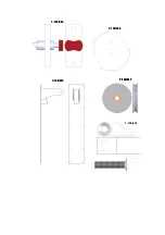
Страница 3: ...N1 N2 W Q H P V S R F J U L T R1 N1 N2 W N1 N2 N1 N2 W Q H P Q H P V S R F J U L T R1...

Страница 4: ...A B T 109 016 T 109 004 A B T 109 016 T 109 004...

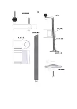
Страница 5: ...012 T 109 016 T 109 001 T 109 014 ACC 26 ACC 29 T 109 009 T 109 010 C T 108 031 T 109 033 T 109 015 T 109 011 T 109 006 T 109 034 T 109 005 T 109 007 ACC 13 ACC 21 ACC 18 T 109 013 T 109 012 T 109 016...

Страница 6: ...CC 26 T 109 002 T 109 026 ACC 26 T 109 020 T 109 017 T 109 020 B T 109 029 T 109 003 T 109 033 A ACC 26 T 109 002 T 109 026 ACC 26 T 109 020 T 109 017 T 109 017 T 109 020 B T 109 029 T 109 003 T 109 0...

Страница 7: ...T 109 018 T 109 032 T 109 019 T 109 026 T 109 021 T 109 022 T 109 027 T 109 018 T 109 032 T 109 019 T 109 026 T 109 021 T 109 022 T 109 027 T 109 027...

Страница 8: ...T 109 017 T 109 025 T 109 028 T 109 004 T 109 034 T 109 017 T 109 017 T 109 025 T 109 028 T 109 004 T 109 034...

Страница 9: ...T 109 024 ACC 14 002 ACC 14 001 ACC 14 ACC 14 002 T 109 024 ACC 14 003 ACC 14 003 C T 109 024 ACC 14 002 ACC 14 002 ACC 14 001 ACC 14 ACC 14 002 T 109 024 ACC 14 003 ACC 14 003 C...

Страница 10: ...nima elevable de 25 Kg 2 3 Altura m xima 7 9 m 2 4 Altura m nima 2 00 m Altura m nima para la carga 0 20 m 2 5 rea de la base 2 17 x 1 83 m 2 6 rea de la base cerrada 0 57 x 0 68 m 2 7 Peso 237 Kg 2...

Страница 11: ...ido y acabado anodizado tambi n en color negro 2 17 Dispositivo de conexi n de toma a tierra ACC 29 2 18 Ruedas direccionales para el transporte de la torre en posici n vertical y plegada hasta su emp...

Страница 12: ...n caso de ser necesario se deber conectar la torre a tierra a trav s del dispositivo de conexi n habilitado para ello ACC 29 3 6 No usar escaleras encima de la torre ni apoyarlas en ella 3 7 Cuidado c...

Страница 13: ...e la parte frontal y las patas cortas sobre la parte trasera FIGURA 1 Introducir las Patas Comprobar los Gatillos de Seguridad 4 3 Ajustar la posici n vertical de la torre mediante los platillos de ap...

Страница 14: ...a U quitando los pasadores L y colocarlos en posici n para soportar la carga Colocar los pasadores de seguridad FIGURA 3 Desbloquear Gatillo R1 Quitar los pasadores L Sacar las horquillas de carga U P...

Страница 15: ...e la carga 4 6 Elevaci n Comprobar que la posici n del Sistema de Seguridad Autom tico SSA del ltimo tramo se encuentra liberado Posici n 1 Elevar la torre girando la manivela del cabestrante W en el...

Страница 16: ...cabrestante y elevaci n del carro Altura m xima del carro sobre el ltimo tramo Bloquear SSA del ltimo tramo Posici n 2 SSA bloqueado Liberaci n SSA Tramo Intermedio Paso 1 Liberaci n SSA Tramo Interm...

Страница 17: ...d de cada tramo FIGURA 7 Posici n de la torre elevada La torre puede dejarse en cualquier posici n intermedia que se necesite ajustando la altura a uno de los alojamientos del Sistema de Seguridad Se...

Страница 18: ...vayan bajando los diferentes tramos hasta que la torre quede completamente plegada a su altura m nima Teniendo en cuenta de mantener sujeto cada SSA conforme se van bajando los tramos FIGURA 8 Giro de...

Страница 19: ...mos Hay que bloquear todos los tramos con los SSA y el carro hay que fijarlo mediante el Gatillo de Seguridad R1 Desmontar las patas liberando los gatillos de retenci n y colocarlas en su posici n de...

Страница 20: ...han sido engrasados con una grasa especial resistente al calor y la presi n No deben ser utilizados otros productos distintos al original suministrado por la empresa para evitar influir negativamente...

Страница 21: ...a sujetacable Acero Zincado Negro T 109 021 Polea nylon Nylatron Nylatron T 109 022 Juego tornillo polea nylon Acero Zincado T 109 023 Tapon Nylon Nylon Blanco T 109 024 Usillopata Zamak Zamak T 109 0...

Страница 22: ...ures and gadgetry of illumination 2 1 Max load 320 kg 2 2 Min load 25 kg 2 3 Max height 7 9 m 2 4 Min height 2 00 m Minimal height for the load 0 20 m 2 5 Base area 2 17 x 1 83 m 2 6 Folded base area...

Страница 23: ...not use stairs upon the tower neither lean them in it 3 7 Be careful with cables prominent objects etc placed above the tower 3 8 Do not stay under the load 3 9 Do not move the tower when it is lifte...

Страница 24: ...blocked Position 1 Lift the tower turning the winch s handle in clockwise N1 raising the load to the required height At the beginning the carriage will lift until the maximum height of the last profil...

Страница 25: ...recommended greasing periodically according to the use the crown wheel of the winch pads of the axle of actuating and the bushing the thread of the handle and the profiles of the tower ATTENTION Do no...

Страница 26: ......

Страница 27: ...y fabricaci n han sido tenidos en cuenta tanto en su totalidad como parcialmente los aspectos recogidos en las normas armonizadas siguientes UNE EN ISO 12100 1 2004 Seguridad de las m quinas Conceptos...

Отзывы: