Recommended Maintenance
The DB10 switch requires no maintenance.
The dryer exhaust duct will require periodic cleaning to remove any
accumulated lint. Time between cleaning intervals will depend on usage
and any suggested guidelines from the dryer manufacturer.
The fan can be removed from the outside wall to facilitate cleaning of
the duct.
The external fan cover can be removed to clean the impeller without
removing the fan from its installed position.
Disconnect the power supply before removing the fan or its cover.
The external cover must be in place for the fan to work properly.
Troubleshooting
Important Notice: Prior to performing Steps 1 - 4, be certain that the
electrical supply to the fan/switch is turned off.
If fan fails to start when the dryer cycle begins, please follow the proce-
dure listed below:
1. Check the incoming supply for proper voltage.
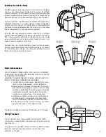
2. Consult schematic shown on Page 3 of these instructions to ensure
proper connection.
3. If possible, use a meter to test for continuity across the fan motor
leads. In order to do this, the capacitor and pressure switch must
be disconnected (do not test the capacitor - it will not meter conti-
nuity). If motor leads show continuity, rewire the fan, capacitor and
pressure switch.
4. Turn on the electrical supply and restart the dryer cycle. Check to be
certain that fan starts.
If fan still fails to start after performing Steps 1 - 4, continue
following the procedure as listed below:
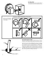
5. Verify that the pressure switch diaphragm is vertical as illustrated on
Page 2 of these instructions. If the diaphragm is not vertical, repo-
sition the pressure switch and check for fan operation against anoth-
er dryer cycle.
6. Verify that pressure tube is not crimped or obstructed and that it is
sealed tight where it enters the dryer duct.
7. If switch diaphragm is vertical and fan still fails to start, with electri-
cal supply connected, remove end of tube from where it is inserted
into dryer duct. Blow into the tube and maintain pressure for more
than five seconds after the switch clicks. This action should start the
fan. Once it starts, it should complete two five minute cycles sepa-
rated by a period of 20 to 30 seconds.
8. If fan fails to start after blowing into the pressure tube:
a. Disconnect incoming power supply at the source.
b. Remove the pressure switch leads from the wiring terminal block
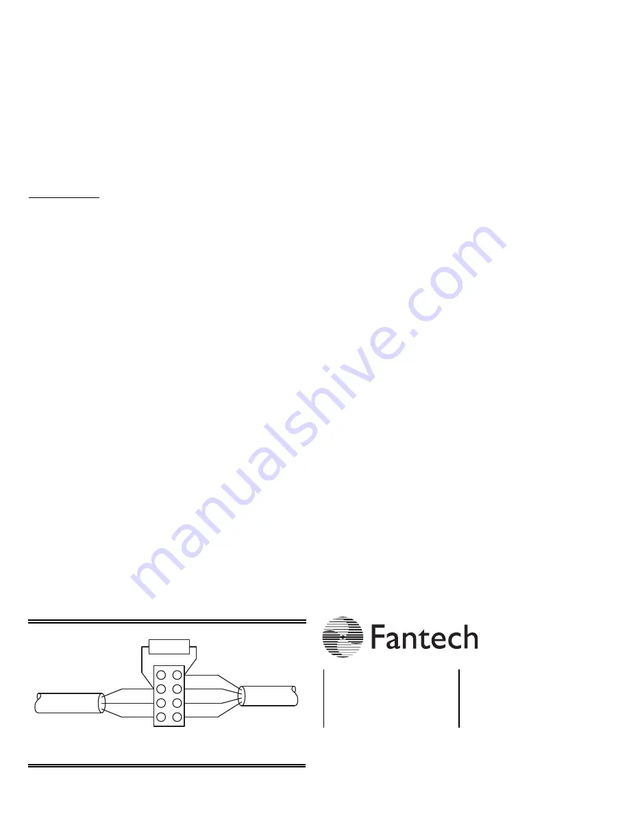
c. Connect the incoming power supply directly to the fan motor as
shown in Fan Wiring Diagram below.
d. Turn on power to fan.
9. If fan fails to start, please consult Fantech for additional
technical support.
Fan Wiring Diagram
LINE
NEUTRAL
GROUND
POWER SUPPLY
115 VAC
BLACK
BLUE
GREEN
BROWN
FAN MOTOR
WIRES
CAPACITOR
Fan Wiring - Fan Only - Reference
for Troubleshooting Step 8.c.
Fantech, reserves the right to modify, at any time and without notice, any
or all of its products’ features, designs, components and specifications to
maintain their technological leadership position.
Item #: 412811 • Rev Date: 040109
United States
10048 Industrial Blvd.
Lenexa, KS 66215
Phone: 800.747.1762; 913.752.6000
Fax: 800.487.9915; 913.752.6466
Canada
50 Kanalflakt Way,
Bouctouche, NB E4S 3M5
Phone: 800.565.3548; 506.743.9500
Fax: 877.747.8116; 506.743.9600
FIVE (5) YEAR WARRANTY
This warranty supersedes all prior warranties
DURING ENTIRE WARRANTY PERIOD:
FANTECH will repair or replace any part which has a factory defect in
workmanship or material. Product may need to be returned to the fan-
tech factory, together with a copy of the bill of sale and identified with
RMA number.
FOR FACTORY RETURN YOU MUST:
Have a Return Materials Authorization (RMA) number. This may be
obtained by calling FANTECH at 1.800.747.1762. Please have bill of
sale available.
• The RMA number must be clearly written on the outside of the car-
ton, or the carton will be refused.
• All parts and/or product will be repaired/replaced and shipped back
to buyer; no credit will be issued.
OR
The Distributor may place an order for the warranty part and/or product
and is invoiced. The Distributor will receive a credit equal to the invoice
only after product is returned prepaid and verified to be defective.
FANTECH WARRANTY TERMS DO NOT PROVIDE FOR REPLACE-
MENT WITHOUT CHARGE PRIOR TO INSPECTION FOR A DEFECT.
REPLACEMENTS ISSUED IN ADVANCE OF DEFECT INSPECTION ARE
INVOICED, AND CREDIT IS PENDING INSPECTION OF RETURNED
MATERIAL. DEFECTIVE MATERIAL RETURNED BY END USERS
SHOULD NOT BE REPLACED BY THE DISTRIBUTOR WITHOUT
CHARGE TO THE END USER, AS CREDIT TO DISTRIBUTOR'S
ACCOUNT WILL BE PENDING INSPECTION AND VERIFICATION OF
ACTUAL DEFECT BY FANTECH.
THE FOLLOWING WARRANTIES DO NOT APPLY:
• Damages from shipping, either concealed or visible. Claim must be
filed with freight company.
• Damages resulting from improper wiring or installation.
• Damages or failure caused by acts of God, or resulting from
improper consumer procedures, such as:
1. Improper maintenance
2. Misuse, abuse, abnormal use, or accident, and
3. Incorrect electrical voltage or current.
• Removal or any alteration made on the FANTECH label control num-
ber or date of manufacture.
• Any other warranty, expressed, implied or written, and to any con-
sequential or incidental damages, loss or property, revenues, or
profit, or costs of removal, installation or reinstallation, for any
breach of warranty.
WARRANTY VALIDATION
• The user must keep a copy of the bill of sale to verify purchase date.
• These warranties give you specific legal rights, and are subject to
an applicable consumer protection legislation. You may have addi-
tional rights which vary from state to state.
4


