fann 35A Скачать руководство пользователя страница 9


Model 35 Viscometer Instruction Manual


208878 

Revision N, February 2013 

9  

Features and Specifications 

The Fann direct-indicating viscometers are equipped with the standard R1 rotor 
sleeve, B1 bob, F1 torsion spring, and a stainless steel sample cup. Other rotor-bob 
combinations and/or torsion springs can be substituted to extend the torque 
measuring range or increase the sensitivity of the torque measurement. 

Each viscometer is supplied with a 115 volt motor. For operation on 230 volts, a 
step-down transformer is required. 

The viscometers are available in six-speed and twelve-speed models.                   
See Table 3-1, 3-2, 3-3, and 3-4 for specifications. Table 3-5 lists the recommended 
environmental conditions for use. 

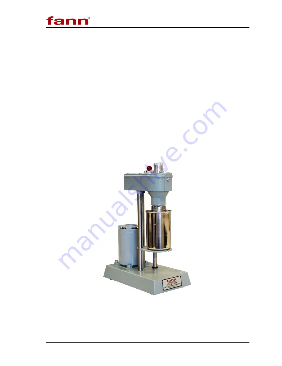
Figure 3-1 is a picture of the viscometer and Figure 3-2 is a detailed drawing that 
names the individual parts. 


Figure 3-1 Model 35SA Viscometer 

Содержание 35A

Страница 1: ...Model 35 Viscometer Instruction Manual Manual No 208878 Revision N Models 35A 35SA 35A SR 12 and 35SA SR 12 ...

Страница 2: ... be covered by U S Patents Fann Instrument Company reserves the right to make improvements in design construction and appearance of our products without prior notice FANN and the FANN logo are registered trademarks of Fann Instrument Company in the United States and or other countries All other trademarks mentioned in the operating instructions are the exclusive property of the respective manufact...

Страница 3: ...5 5 3 Measuring Gel Strength 17 5 4 Changing the Rotors Bobs and Torsion Springs 18 6 Instrument Calibration Check 23 6 1 Dead Weight Calibration 24 6 2 Fluid Calibration Check 26 6 3 Torsion Spring Calibration 27 7 Test Analysis 28 7 1 Newtonian Viscosity Calculation 28 7 2 Plastic Viscosity and Yield Point Calculation 29 7 3 Spring Constant Calculation 30 7 4 Additional Viscosity Calculations 31...

Страница 4: ...ge of Environmental Conditions 12 Table 5 1 Six Speed Testing Combinations for Models 35A and 35SA 15 Table 5 2 Twelve Speed Testing Combinations Models 35A SR 12 and 35SA SR 12 16 Table 6 1 Dial Deflection for Calibration Weights and Torsion Spring Assemblies 25 Table 7 1 Rotor Bob Factor C 29 Table 7 2 Speed Factor S 29 Table 7 3 Torsion Spring Specifications 30 Table 7 4 Constants for Viscosity...

Страница 5: ... and the bob inner cylinder Viscosity measurements are made when the outer cylinder rotating at a known velocity causes a viscous drag exerted by the fluid This drag creates a torque on the bob which is transmitted to a precision spring where its deflection is measured Viscosity measured by a Couette viscometer such as the Model 35 is a measure of the shear stress caused by a given shear rate This...

Страница 6: ...perator awareness or action in order to avoid undesirable consequences MANDATORY ACTION Gives directions that if not observed could result in loss of data or in damage to equipment WARNING Describes an unsafe condition or practice that if not corrected could result in personal injury or threat to health ELECTRICITY WARNING Alerts the operator that there is risk of electric shock HOT SURFACE Alerts...

Страница 7: ...electrical power Keep hands clothes and other objects away from the rotating parts of the machine The optional heated sample cups and recirculating sample cups are electrically heated Make sure the power cord and other wiring associated with these cups and the Model 35 assembly is in good condition and properly grounded Make sure the viscometer s power switch is the OFF position and unplugged from...

Страница 8: ...ries viscometers is a hollow bob that must not be used to test samples hotter than 200 F 93 C Solid bobs are available for testing at higher temperatures 2 3 Heated Sample Cup When testing heated samples using the heated sample cups wear the proper hand protection to avoid getting burned When using heated sample cups do NOT exceed 200o F 93o F ...

Страница 9: ...xtend the torque measuring range or increase the sensitivity of the torque measurement Each viscometer is supplied with a 115 volt motor For operation on 230 volts a step down transformer is required The viscometers are available in six speed and twelve speed models See Table 3 1 3 2 3 3 and 3 4 for specifications Table 3 5 lists the recommended environmental conditions for use Figure 3 1 is a pic...

Страница 10: ...Model 35 Viscometer Schematic Gear Shift Knob Gel Knob Coupling Stop Motor Speed Switch 2 Speed Motor Torsion Spring Assembly Lens Dial Pointer Gas Purge Nipple optional Bob Shaft Bearings Splash Guard Scribed Line Bob Shaft Bob Circulating Cup Sample Fill Line 350 ml Locking Knob Stage ...

Страница 11: ...10 5 in 39 x 15 x 27 cm 15 lb 6 8 kg 35SA SR 12 207201 15 2 x 6 x 10 5 in 39 x 15 x 27 cm 15 lb 6 8 kg 35A w case 101671768 8 x 16 x 19 in 20 3 x 40 6 x 48 3 cm 26 lb 11 8 kg 35SA w case 101671770 8 x 16 x 19 in 20 3 x 40 6 x 48 3 cm 26 lb 11 8 kg Model No Part No Electrical No of Speeds Speeds 35A 207198 115V 60 Hz 90W 6 600 300 200 100 6 3 35SA 207199 115V 50 Hz 90W 6 600 300 200 100 6 3 35A SR ...

Страница 12: ...17 0 0343 0 8261 0 6139 0 9793 0 9793 Radii Ratio Ri R0 0 9365 0 9805 0 667 0 666 0 468 0 468 Maximum Use Temperature o C 93 93 93 93 93 93 Minimum Use Temperature o C 0 0 0 0 0 0 Table 3 5 Range of Environmental Conditions Unit Radius cm Length cm Cylinder Area cm2 x Radius cm B1 1 7245 3 8 71 005 B2 1 2276 3 8 35 981 B3 0 86225 3 8 17 751 B4 0 86225 1 9 8 876 R1 1 8415 n a n a R2 1 7589 n a n a ...

Страница 13: ...be placed in a position where there is easy access to the power cord plug for disconnection Consideration should be given to the location where samples are prepared and equipment is cleaned when the test is completed There should be sufficient storage area nearby for commonly used tools as well as consumables ...

Страница 14: ...d sample to the stainless steel sample cup The sample cup has a line that marks 350 ml as shown in Figure 3 2 A scribed line on the rotor indicates proper immersion depth Refer to Figure 3 2 Damage to the bob shaft bearings may occur if this immersion depth is exceeded If other sample holders are used the space between the bottom of the rotor and the bottom of the sample holder should be one half ...

Страница 15: ... the motor is running Read the dial for shear stress values Table 5 1 Six Speed Testing Combinations for Models 35A and 35SA Speed RPM Viscometer Switch Gear Shift Knob 600 High Down 300 Low Down 200 High Up 100 Low Up 6 High Center 3 Low Center 5 2 Operating the Model 35A SR 12 and 35SA SR 12 The Model 35A SR 12 and 35SA SR 12 have twelve speeds for testing capabilities To achieve this broader te...

Страница 16: ... of gear box shift lever setting speed switch selection and viscometer gear shift knob placement The shear stress values will appear on the dial Figure 5 1 Gear Box Shift Lever Table 5 2 Twelve Speed Testing Combinations Models 35A SR 12 and 35SA SR 12 RPM Gear Box Shift Lever Speed Switch Gear Shift Knob 600 Left High Down 300 Left Low Down 200 Left High Up 180 Right High Down 100 Left Low Up 90 ...

Страница 17: ... time turn the motor to the ON position at low speed 4 Read the dial at the moment the gel breaks as noted by a peak dial reading The gel strength units are lb 100ft2 An alternative method for measuring gel strength is as follows 1 Stir the sample thoroughly at 600 rpm 2 Turn the motor to the OFF position 3 After the desired wait period turn the gel knob located below the gear shift knob slowly co...

Страница 18: ...tor bob combinations other than R1 B1 have large gap sizes as a result the shear stress dial readings are not consistent with readings from a smaller gap The following instructions explain how to remove and replace the rotors bobs and torsion springs Calibration is required when torsion springs are changed Changing the rotors and bobs only reconfigures the geometry of the shear gap These changes d...

Страница 19: ...eplace the rotor align the rotor slot and groove with the lock pin in the main shaft socket Then push the rotor upward and turn it counterclockwise locking it into position Figure 5 2 Rotor Removal and Installation Main Shaft Lock Pin Slot and Groove Rotor To remove rotor Rotate clockwise and pull down To replace rotor Align slot and groove with lock pin then push upward and lock into place by tur...

Страница 20: ...s tapered and fits into a matching tapered hole in the bob Refer to Figure 5 3 1 Rotate the rotor clockwise and gently pull it down to remove it 2 To remove the bob twist it clockwise while pulling down 3 To install the bob twist it clockwise while pushing upward Figure 5 3 Bob and Bob Shaft Bob Shaft Bob Type B 1 hollow shown ...

Страница 21: ...andrel will help locate this point Tighten set screw D so that it presses against the split ring to hold the bottom mandrel of the spring Before tightening the set screw C make sure that the top of the adjustable mandrel is flush with the top of the clamp E You may need to slightly compress or stretch the spring to accomplish this 4 Tighten the set screw C The slot in the top of the adjustable man...

Страница 22: ...Model 35 Viscometer Instruction Manual 208878 Revision N February 2013 22 Figure 5 4 Torsion Spring Removal and Replacement A G E C F B D ...

Страница 23: ...rated In accordance with API 13B 1 and 13B 2 Fann recommends calibrating the Model 35 before it is placed in service and at least monthly while it is in service However calibration frequency depends on your usage and laboratory quality assurance program The calibration is checked by applying known torques to the bob shaft For any applied torque within the torque range of the spring there should be...

Страница 24: ...nual 208878 Revision N February 2013 24 6 1 Dead Weight Calibration This procedure uses the Model DW3 Calibration Kit P N 207853 Refer to Figure 6 1 Figure 6 1 DW3 Calibration Fixture Calibrating Spool Calibrating Fixture Pulley Weight ...

Страница 25: ...f necessary adjust the torsion spring as specified in Section 6 3 From Table 6 1 the factory tolerances for F1 spring only are 127 1 2 for 50 grams and 254 1 2 for 100 grams A movement of 1 2 is permissible when the main shaft is turning This movement will generally be dampened out when a fluid is being tested Check the linearity of the dial reading with at least three weights If the spring appear...

Страница 26: ... rotor is immersed to the proper immersion depth Refer to Figure 3 2 3 Place a thermometer into the sample cup until it touches the bottom and then secure it to the side of the viscometer to prevent breakage 4 Operate the instrument at 100 rpm for approximately three minutes This will equalize the temperature of the bob rotor and the fluid 5 Read the dial at 300 rpm and 600 rpm Record these number...

Страница 27: ...ibration tool into the spring and rotate the adjustable mandrel inside the spring slightly Turn the mandrel counterclockwise if the dial reading is too low or turn the mandrel clockwise if the dial reading is too high Before tightening set screw C check the top of the center mandrel and be sure that it is flush with the top of the clamp E To accomplish this it may be necessary to adjust the spring...

Страница 28: ...t the dial reading is multiplied by the f factor spring constant to calculate the viscosity To calculate Newtonian viscosities in centipoise with the Fann viscometer use the following equation ƞN S x θ x f x C Equation 7 1 where S is the speed factor Refer to Table 7 2 θ is the dial reading f is the spring factor Refer to Table 7 3 C is the rotor bob factor Refer to Table 7 1 ƞN is the Newtonian v...

Страница 29: ...lation Using R1 B1 F1 combination test a sample at 600 rpm and record the dial reading Change the speed to 300 rpm and record the dial reading Determine the plastic viscosity PV and yield point YP using the following equations PV represents the slope of a straight line between the two dial readings YP represents the theoretical point at which the straight line when projected will intercept the ver...

Страница 30: ...equired setting for the F1 spring is 386 dynes cm degree deflection with the R1 B1 combination Using the 50 gram weight supplied with the calibration kit the spring constant is 127 386 981 1 50 Ks Table 7 3 Torsion Spring Specifications Torsion Spring Assembly Torsion Spring Constant k1 dyne cm degree deflection Torsion Spring Factor f Maximum Shear Stress with B1 Bob dyne cm 2 Color Code F0 2 77 ...

Страница 31: ...e overall instrument constant that matches the rotor bob combination in Table 7 4 Choose the f constant that matches the torsion spring assembly in Table 7 3 For Equation 7 5 choose the correct K value overall instrument constant that matches the rotor bob combination in Table 7 4 Choose the f constant that matches the torsion spring assembly in Table 7 3 η k1k2 k3 100 θ N Equation 7 6 where k1 is...

Страница 32: ...e Constant k3 sec 1 per rpm 1 7023 5 4225 0 377 0 377 0 268 0 268 Shear Stress Constant for Effective Bob Surface k2 cm 3 0 01323 0 01323 0 01323 0 0261 0 0529 0 106 Table 7 5 Conversion Factors Symbol Unit Conversion Factor SI Units Shear Stress τ Pa Newton m 2 1 Pa 10 dynes cm 2 Shear Rate γ s 1 1 s 1 no change Viscosity ƞ Pa s mPa s 1 Pa s 10 poise 1 mPa s 1 cP Oilfield Units R1 B1 F1 Shear Str...

Страница 33: ...2 1 02 1 02 2 01 4 1 8 2 θ 300 o 307 307 307 605 1225 2450 F 0 5 θ 1 o 2 56 2 56 2 56 5 04 10 2 20 4 θ 300 o 766 766 766 1510 3060 6140 F1 θ 1 o 5 11 5 11 5 11 10 1 20 4 40 9 θ 300 o 1533 1533 1533 3022 6125 12 300 F2 θ 1 o 10 22 10 22 10 22 20 1 40 8 81 8 θ 300 o 3066 3066 3066 6044 12 250 24 500 F3 θ 1 o 15 3 15 3 15 3 30 2 61 3 123 θ 300 o 4600 4600 4600 9067 18 400 36 800 F4 θ 1 o 20 4 20 4 20...

Страница 34: ... Rotor Bob Combinations R1 B1 R2 B1 R3 B1 R1 B2 R1 B3 R1 B4 0 9 1 5 4 9 0 4 0 4 0 24 0 24 1 8 3 1 9 8 0 7 0 7 0 48 0 48 3 5 1 16 3 1 1 1 1 0 8 0 8 6 10 2 32 5 2 3 2 3 1 61 1 61 30 51 1 163 11 3 11 3 8 8 60 102 325 22 6 22 6 16 1 16 1 90 153 488 33 9 33 9 24 1 24 1 100 170 542 37 7 37 7 26 8 26 8 180 306 976 67 9 67 9 48 2 48 2 200 340 1084 75 4 75 4 53 6 53 6 300 511 1627 113 113 80 4 80 4 600 102...

Страница 35: ...imum Viscosity 4 30 000 9 400 135 000 270 000 762 000 1 500 000 Model 35A SR 12 35SA SR 12 0 9 rpm min Maximum Viscosity 4 100 000 31 400 400 000 890 000 2 550 000 5 000 000 Notes 1 Computed for standard Torsion Spring F1 For other torsion springs multiply viscosity range by f factor 2 Minimum viscosity is computed for minimum shear stress and maximum shear rate 3 For practical purposes the minimu...

Страница 36: ...t Rotor out of alignment Replace the rotor if it is damaged See list of rotors in Table 9 1 Out of calibration Contaminated bob shaft bearings Replace the bob shaft bearings P N 207450 Bent bob shaft Bend shaft slightly to straighten it Contact Fann for repair or replacement Bent rotor Replace the rotor See Table 9 1 Damaged or incorrectly installed torsion spring See Section 5 4 to replace the to...

Страница 37: ...lean the bob and rotor after each test Periodically examine the bob and rotor for dents abrasion or other damage Always remove the bob from the bob shaft when transporting instrument to avoid bending bob shaft Periodically test the bob shaft bearings Operate the instrument at 3 rpm or 6 rpm without sample Observe movement of the dial It should not move more than 1 division Rough bob shaft bearings...

Страница 38: ...less Steel Solid 207519 B3 303 Stainless Steel Solid 207518 B4 303 Stainless Steel Solid Sample Cups 101558383 Thermocup 115 Volts 50 60 Hz 2 amps 200 o F 101558384 Thermocup 230 Volts 50 60 Hz 1 amp 200 o F 207958 Double Wall Circulating Cup 207560 Stainless Steel Sample Cup Circulators 208754 Heat only Circulator 90 F to 212 F 4 liters 115 Volts 60 Hz 1 000 Watt 208755 Cooling Heating Circulator...

Страница 39: ...rs are combined in Table 10 2 See Figure 10 1 the upper half of the Model 35 for identification numbers 1 24 and 43 69 in the parts list See Figure 10 2 the lower half of the Model 35 for identification numbers Table 10 1 Model 35 Series Viscometers Model No Part No Electrical 35A 207198 115V 60 Hz 90W 35SA 207199 115V 50 Hz 90W 35A SR 12 207200 115V 60 Hz 90W 35SA SR 12 207201 115V 50 Hz 90W ...

Страница 40: ...Model 35 Viscometer Instruction Manual 208878 Revision N February 2013 40 Figure 10 1 Model 35A and 35SA Upper ...

Страница 41: ...Model 35 Viscometer Instruction Manual 208878 Revision N February 2013 41 Figure 10 2 Model 35A and 35SA Lower ...

Страница 42: ...taining Ring 2 17 207965 Main Shaft 18 207449 Main Shaft Bearing 2 19 207450 Bob Shaft Bearing 2 20 207546 Bearing Shield 21 205697 External Retaining Ring 22 207539 Splash Guard 23 207523 Rotor R 1 24 207521 Bob B 1 25 207597 Clamp Nut 26 207598 Clamp Spacer 27 207588 Clamp Screw 28 207153 Drive Shaft Tube 29 207599 Support Rod 2 30 207593 Stop Collar 31 207437 Bearing 32 207564 Drive Shaft Gear ...

Страница 43: ...r for Jackshaft Assembly 56f 207437 Bearing 56g 207814 External Retainer 57 207428 Spacer 58 207437 Bearing 59 207143 Internal Retaining Rings 60 207567 Clutch Spring 61 207545 Upper Drive Shaft 62 208002 Thrust Washer 63 207778 Shim 64 207817 Flat Washer 65 207152 Flex Coupling 66 207452 Bushing 67 207558 Lower Drive Shaft 68 207487 Stop Screw 69 207514 Center Shaft Gear Assembly 70 207446 Motor ...

Страница 44: ...anty statement enclosed with the product 11 2 Returns For your protection items being returned must be carefully packed to prevent damage in shipment and insured against possible damage or loss Fann will not be responsible for damage resulting from careless or insufficient packing Before returning items for any reason authorization must be obtained from Fann Instrument Company When applying for au...

Отзывы: