


10
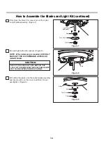
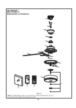
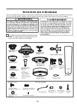
How to Hang Your Ceiling Fan
(continued)
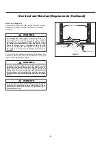
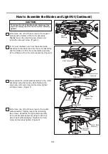
5.
Attach the safety cable to ceiling support cable.
Slide cable clamp and washer onto safety cable
(from fan). Place the end of cable through the loop of
ceiling support cable. Pull as much cable through loop
as possible. Feed end of cable into clamp hole and
firmly tighten screw. (Figure 4)
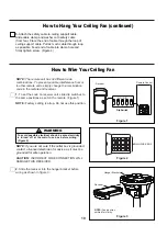
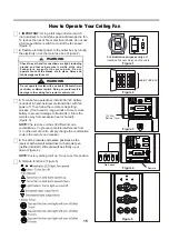
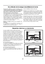
How to Wire Your Ceiling Fan
NOTE:
Factory setting is all up. Do not use this position.
1.
To set the code on receiver unit, slide dip switches to
the same positions as set on the remote. (Figure 1)
NOTE: The remote unit has 32 different code
combinations. To prevent possible interference from or
to other remote units, simply change the combination
code in the remote and receiver.
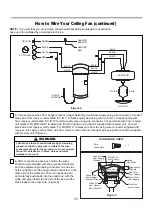
To avoid possible electrical shock, be sure electricity
is turned off at the main fuse box before wiring.
(Figure 2)
WARNING
CAUTION:
INCORRECT WIRE CONNECTION WILL
DAMAGE THIS RECEIVER.
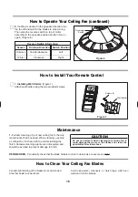
NOTE:
If you are not sure if the outlet box is grounded,
contact a licensed electrician for advice, as it must be
grounded for safe operation.
Hanger Bracket
Receiver
NOTE:
Supply wires
omitted for clarity.
MAIN FUSE BOX
Figure 2
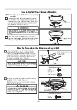
Figure 3
Figure 1
Dip Switch
Receiver
Remote Control
ON DIP
1
2
3
4
5
2.
Slide the receiver into the hanger bracket before
wiring as shown in figure 3.