background image

13

How to Operate Your Ceiling Fan

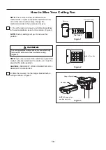
Figure 1

For illustrative purposes only

-not

intended to cover all types of controls

1. 

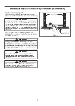
IMPORTANT: Using a full range dimmer switch (not 

included) to control fan speed will damage the fan. To 

reduce the risk of fire or electrical shock, do not use a 

full range dimmer switch to control the fan speed.

(Figure 1)

Figure 2

Main Fuse Box

2. 

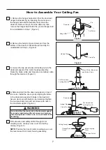
Restore electrical power to the outlet box by turning

the electricity on at the main fuse box. (Figure 2)

WARNING

Check to see that all connections are tight, including

ground, and that no bare wire is visible at the wire

connectors, except for the ground wire. Do not operate 

fan until the blades are in place. Noise and fan damage 

could result.

WARNING

Do not operate this fan with a variable (Rheostat) wall

controller or dimmer switch. Doing so could result in

damage to the ceiling fan's remote control unit.

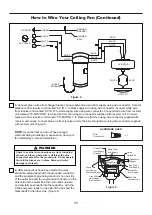
12V 23A

Battery (1 pcs)

Figure 3

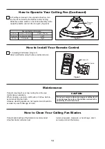
3. 

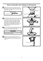
To make fan operational, install 23A/12V battery

(included) in hand-held remote transmitter, with fan

power off. Then follow the remote code setting process. 

(If not used for long periods of time, remove battery to 

prevent damage to transmitter). Store the remote away 

from excessive heat or humidly. (Figure 3)

NOTE: 

The remote unit has 32 different code

combinations. To prevent possible interference from 

or to other remote units, simply change the 

combination code in the remote and receiver.

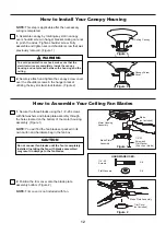
4. 

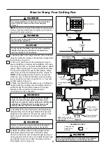
To set the remote code in the same positions as

the receiver, use a small screwdriver or ball point pen

(neither included) to slide dip switches firmly up or

down. (Figure 4)

NOTE: 

Factory setting is all up. Do not use this position.

Figure 4

Remote

Dip Switch

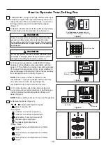
•                  Indicator LED light: fan speed
•       button: Turns fan off.
• Fan Speed:
         Turns fan on and turns speed up.
         Turns fan on and turns speed down.
•        Light button: Turns light on and off.
         Increases light output level.
         Decreases light output level.
• Sleep Timer:
         Tap and the fan and light will turn off after

         1 hour.
         Tap and the fan and light will turn off after

         3 hours.
         Tap and the fan and light will turn off after

         6 hours.

5. 

Remote functions: (Figure 5)

Figure 5

ON    DIP

1

2

3

4

5

Содержание SPITFIRE MA6721B Series

Страница 1: ...chase Date ATTACH YOUR RECEIPT HERE AND REGISTER YOUR FAN AT FANIMATION COM READ AND SAVE THESE INSTRUCTIONS Net Weight 16 34 lbs 7 41 kgs SPITFIRE CEILING FAN MODEL MA6721B Espa ol p 20 For best and...

Страница 2: ...grounded conductor power supply If the conductor of a fan is identified as an ungrounded conductor then it should be connected to an ungrounded conductor power supply If the conductor of a fan is iden...

Страница 3: ...erves the right to modify or discontinue any product at any time and may substitute any part under this warranty 8 Under no circumstances may a fan be returned without prior authorization from Fanimat...

Страница 4: ...ct and or any accessories designated specifically for use with this product by Fanimation Substitution of parts or accessories not designated for use with this product by Fanimation could result in pe...

Страница 5: ...ur Fanimation Retailer for optional mounting accessories Turn Off When Not in the Room Ceiling fans cool people not rooms If the room is unoccupied turn off the ceiling fan to save energy Your new cei...

Страница 6: ...of wooden blocking To avoid fire or shock follow all wiring instructions carefully Any electrical work not described in these instructions should be done or approved by a licensed electrician Figure 3...

Страница 7: ...ly removed set screws with nuts in the downrod support Figure 4 2 Remove the hairpin clip and clevis pin from the bottom of the downrod Retain the pin and clip for reinstallation in Step 4 Figure 2 Fi...

Страница 8: ...ve top of the downrod Strip insulation off 1 2 inch from the end of each lead wire Figure 8 How to Assemble Your Ceiling Fan Continued 6 t o 9 i n Figure 7 Figure 8 Figure 9 9 Remove one of the two sh...

Страница 9: ...racket grounding wire and safety cable are pulled through the downrod between the hanger bracket and the outlet box so that electrical connections can be made later 4 Carefully lift the fan and seat t...

Страница 10: ...tact a licensed electrician for advice as it must be grounded for safe operation CAUTION INCORRECT WIRE CONNECTION WILL DAMAGE THIS RECEIVER 1 To set the code on receiver unit slide dip switches to th...

Страница 11: ...and that no bare wire is visible at the wire connectors except for the ground wire Do not operate fan until the blades are in place Noise and motor damage could result 4 After connections have been ma...

Страница 12: ...emble Your Ceiling Fan Blades 1 4 20 Screws X 6 Flat Washers X 6 HARDWARE USED CAUTION Do not connect fan blades until the fan is completely installed Installing the fan with blades assembled may resu...

Страница 13: ...tery included in hand held remote transmitter with fan power off Then follow the remote code setting process If not used for long periods of time remove battery to prevent damage to transmitter Store...

Страница 14: ...ttach wall holder using the two provided screws Periodic cleaning of your new ceiling fan is the only maintenance necessary When cleaning use only a soft brush or lint free cloth to avoid scratching t...

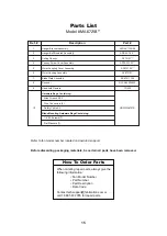
Страница 15: ...P672111NI HDWMA6721B 8 9 Ceiling Canopy Flat Washers 7 Allen Wrench 3 32 Wire Connectors 4 Safety Cable Kit Blade Mounting Hardware Bags Containing 1 4 20 Screws 7 Hardware Bags Containing Motor Housi...

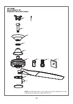
Страница 16: ...E The illustration shown is not to scale or its actual configuration may vary Product parts are subject to change without notice SPITFIRE Model MA6721B Exploded View Illustration 1 2 3 4 5 8 9 10 10 6...

Страница 17: ...stration shown is not to scale or its actual configuration may vary Before discarding packaging materials be certain all parts have been removed How To Order Parts When ordering repair parts always gi...

Страница 18: ...t screws to the timber batten and secure outlet box 1 If possible consider using a longer downrod not included you can buy the longer downrod from fanimation com For your own safety turn off power at...

Страница 19: ...10983 Bennett Parkway Zionsville IN 46077 Phone 888 567 2055 Outside U S 317 733 4113 FAX 866 482 5215 FANIMATION COM 2021 03 V 01 Copyright 2021 Fanimation...

Страница 20: ...C digo de fecha Fecha de compra ADJUNTE SU RECIBO AQU Y REGISTRE SU VENTILADOR EN FANIMATION COM LEA Y GUARDE ESTAS INSTRUCCIONES Para ofrecer un servicio r pido y de calidad por favor suministre el c...

Страница 21: ...producto est dise ado para ser usado s lo con las piezas suministradas o los accesorios indicados espec ficamente para el mismo Si utiliza piezas o accesorios que no est n indicados para su uso con es...

Страница 22: ...animation niega todas las garant as impl citas que incluyen entre otras la comerciabilidad y la aptitud para determinado fin hasta donde la ley lo permita Algunos estados no permiten limitaciones sobr...

Страница 23: ...u de vente en cas de pi ces manquantes ou endommag es Instrucciones para el desempaque Para su comodidad marque cada uno de los pasos A medida que completa cada paso coloque una marca de verificaci n...

Страница 24: ...para un flujo de aire ptimo Consulte en su tienda minorista de Fanimation para obtener accesorios de montaje opcionales Apague el ventilador cuando no se encuentre en la habitaci n Los ventiladores so...

Страница 25: ...A fin de evitar incendios o descargas el ctricas siga con cuidado todas las instrucciones de instalaci n el ctrica Cualquier trabajo el ctrico que no se describa en estas instrucciones deber ser real...

Страница 26: ...illa Figura 3 4 Coloque el soporte de la varilla y alinee los orificios de la clavija de horquilla en ambas piezas Instale la clavija de horquilla y aseg rela con la pinza de horquilla Instale los set...

Страница 27: ...e hombro sin extraiga completamente Figura 9 Unidad del soporte de suspensi n Figura 6 6 Alinee el orificio de la cubierta de uni n del motor sobre el interruptor del reverso desde el unidad del motor...

Страница 28: ...tier fusibles principal avant de suspendre le ventilateur afin d viter tout risque d lectrocution Figure 1 ADVERTENCIA La caja de distribuci n el ctrica de be estar bien asegurada y debe ser capaz de...

Страница 29: ...do que m s tarde se pueda realizar la instalaci n el ctrica 5 Fije el cable de seguridad al cable de soporte para techo Deslice la abrazadera de cables por el cable de seguridad del ventilador Pase el...

Страница 30: ...n a tierra para un funcionamiento seguro PRECAUCI N UNA CONEXI N INCORRECTA DEL CABLE PODR A DA AR ESTE RECEPTOR ATTENTION UNE CONNEXION DE FIL INCORRECTE PEUT ENDOMMAGER CE RECEPTEUR ADVERTENCIA Par...

Страница 31: ...conductor negro del ventilador con el conector de cables que se adjunta con la unidad receptora Finalmente conecte el conductor azul de la unidad receptora al conductor azul de la iluminaci n del ven...

Страница 32: ...instalar la carcasa de la cubierta Cubierta para el tornillo del capuch n Figura 2 Figura 1 NOTA Este paso se debe realizar luego de completar la instalaci n el ctrica necesaria 1 Instale la cubierta...

Страница 33: ...N No conecte las aspas hasta que el ventilador est totalmente instalado Instalar el ventilador con las aspas colocadas podr a ocasionar da os en las mismas ATTENTION Ne raccordez pas les pales du ven...

Страница 34: ...a o hacia abajo Figura 4 NOTA Los ajustes de f bricas vienen con todos los interruptores hacia arriba No utilice esta posici n Luz LED del indicador Velocidad del ventilador Bot n Apaga el ventilador...

Страница 35: ...llos suministrados Tornillos 2 Placa de la pared El nico mantenimiento necesario para el ventilador de techo es una limpieza peri dica Al llevar a cabo la limpieza use s lo un cepillo suave o un pa o...

Страница 36: ...la plana 7 Llave Allen de 3 32 Conectores de cables 4 Kit de cable de seguridad Bolsa de accesorios para el montaje de aspas que contiene Tornillos 1 4 20 7 Bolsa de accesorios que contiene Unidad de...

Страница 37: ...37 Modelo MA6721B Ilustraci n del despiece SPITFIRE NOTA La ilustraci n que se muestra no est hecha a escala y su c guraci n real y o terminaci n puede variar 1 2 3 4 5 8 9 10 10 6 7 10...

Страница 38: ...hecha a escala y su configuraci n real puede variar Antes de desechar los materiales de embalaje aseg rese de haber extra do todas las piezas C mo hacer un pedido de piezas Al hacer un pedido de piez...

Страница 39: ...Asegure bien los tornillos de fijaci n 4 El tornillo del soporte de la cubierta inferior est flojo 4 Ajuste los tornillos del soporte de suspensi n de la caja de distribuci n el ctrica y aseg rela 4 E...

Страница 40: ...ro sitio Web en www fanimation com 10983 Bennett Parkway Zionsville IN 46077 Llame sin cargo al 888 567 2055 FAX 866 482 5215 Desde fuera de los EE UU llame al 317 733 4113 2021 03 V 01 Copyright 2021...

Отзывы: