


24
Figura 1
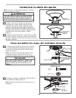
Figura 3
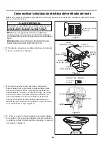
Figura 2
x 3
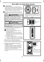
Figura 4
NEGRO
(PARA MOTOR L)
AZUL
(PARA LA LUZ )
BLANCO
(PARA MOTOR N)
NEGRO
(ENTRADA CA N)
BLANCO
(ENTRADA CA N)
ANTENA
NEGRO
NEGRO
NOTA:
Si los cables de suministro o del ventilador son de colores dif
erentes que los indicados, contrate a un electricista calificado
para que realice la instalación.
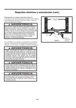
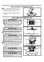
Cómo realizar la instalación eléctrica del ventilador de techo
PRINCIPAL CAJA DE
FUSIBLES
PRECAUCIÓN:
UNA CONEXIÓN INCORRECTA DEL
CABLE PODRÍA DAÑAR ESTE RECEPTOR.
1.
Realice las conexiones de cables al bloque del terminal
como se muestra en la Figura 2.
3.
Una vez que se ha haya realizado la conexión, deslice
el receptor en el soporte del colgador, teniendo cuidado de
no pillar los cables. El dosel cubrirá el receptor y el soporte
del colgador. (Figura 4)
NOTA:
Si no está seguro de si la caja de salida tiene
conexión a tierra, pida consejo a un electricista certificado,
ya que debe tener conexión a tierra para un funcionamiento
seguro.
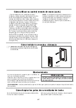
Para evitar una posible descarga eléctrica, asegúrese de
cortar la alimentación eléctrica de la caja de fusibles
principal antes de alambrado el ventilador. (Figura 1)
ADVERTENCIA
2.
Una vez haya hecho las conexiones, coloque los
cables hacia arriba y empújelos cuidadosamente hacia
dentro de la caja de la toma de corriente, poniendo los
cables blancos y verdes a un lado de la caja y los negros
hacia el otro lado. Los cables deben ser colocados de
forma extendida poniendo el conductor de la toma de
tierra y el conductor de toma de tierra del equipo a un
lado de la caja, colocando el conductor sin toma de tierra
en el otro lado de la caja. (Figura 3)
VERDE
BLANCO
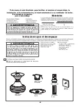
Conectores
de cable
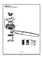
Aditamentos utilizados
Содержание SPITFIRE MA6721 Series
Страница 22: ...22 ...


