


How to Wire Your Ceiling Fan - CW3 Wall Control
Operating Instructions - CW3 Wall Control
If you feel that you do not have enough electrical
wiring knowledge or experience, have your fan
installed by a licensed electrician.
NOTE:
If fan or supply wires are different colors
than indicated, have this unit installed by a quali
fi
ed
electrician.
1.
Operating & Using Wall Control (Figure 1):
2.
Check the operation of the fan by moving the slide
switch on the wall control to low and then to high.
• OFF Switch – fan o
ff
• LO Slide Switch – low fan speed
• HI Slide Switch – hi fan speed
• OFF Switch – fan o
ff
1.
Complete steps 1 thru 6
“How
to Wire Your Ceiling Fan”
from page 8.
2.
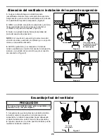
Installing
Wall Control (Figures 1 & 2):
• With electrical power still disconnected, remove the
existing wall plate and switch.
•
Make wiring connections with wire nuts as shown in
Figure 1.
– One black wire from wall control unit to black
(hot supply).
– One black wire from wall control unit to black wire
leading to ceiling outlet box.
•
Attach wall control unit to outlet box using the two
6-32 screws provided.
•
Attach wall plate to the switch control front using the two
small screws provided.
• Restore electrical powe
r.
BLK
TO HOT
GRN from bracket
120 VAC Supply
(User Supplied)
WH-
TO MO
TOR
BLK-
TO MO
TOR
BLUE-Not Used
BLK
TO FAN
BLK
WH
GRN
Figure 1
9
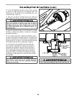
Figure 2
NOTE:
Supply wires and fan wires
omitted for clarity.
Figure 1
▲
WARNING
Check to see that all connections are tight, including
ground, and that no bare wire is visible at the wire
connectors, except for the ground wire. Do not operate
fan until the blades is in place. Noise and fan damage
could result.
▲
WARNING
To avoid possible fire or shock, make sure that the
electrical wires are completely inside the outlet box and
not pinched between the wall plate and the wall.