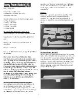


With all the surfaces set to zero, measure the distance
between servo arm holes and control horn holes. Cut a
piece of 1.5mm carbon rod for each push rod to the
measured lengths. Cut a 1.5” long piece of 1/32” wire
and make a z-bend on one end. Slide a pushrod guide
onto the tail pushrods before installing both ends. Slide
a 1” length of heat shrink over each end of the carbon
rod and then slide in a z-bend wire. Shrink the heat
shrink tubing with a heat gun or flame. The z-bend
wire is not glued in position yet and can be moved for
final adjustments.
Remove the servo arm and assemble the pushrods to
the servo arm and control horns. With the servo
centered reattach the servo horn. Make any final
adjustments to the z-bend location. Use regular (not
foam safe) thin CA to secure the z-bends to the push
rods by placing a drop at each end of the heat shrink
tubing. If you get some CA on the servo or control horn
this is ok and moving the controls will allow the z-
bend to break loose.
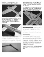
Motor installation
Install the motor into the stick motor mount and velcro
the speed control and receiver to the lower left side of
the fuselage.
Flight set-up:
Use double stick Velcro on the battery and airframe to
secure the battery to the bottom of the horizontal
fuselage in a location that gives the model proper
balance. Adjust the battery location back and forth to
suit your flying style. Use your computer radio to set
the final sub-trims, exponential and dual rates. Double
check the control directions before your first flight.
With proper CG, the plane should fly nearly the
same upright or upside-down.
Good pilots
experiment with various battery locations until the CG
feels just right.
For indoor flying, we use 2 or 3 cell lipo packs rated at
20C. Batteries of 300 to 480 mah are perfect for
giving good flight times and plenty of power. The final
airplane weight should be between 6.0 and 7.5 oz.
Center of Gravity:
Yak-55 is 2.75” behind the leading edge of the wing.
Edge 540 is 3.5” behind the leading edge of the wing.
Freestyle is 3” behind the leading edge of the wing.
We hope you enjoy your airplane.
Thank You,
Mike & Niki Bailey
Fancy Foam Models
4


