background image

Gndfi 


11 

g
 

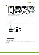
3.  Place the protective screen on the I-fan and fix the protective screen with a M5 x 30 bolt. 


2.4


Test the I-fan 

1.  Check whether the I-fan has been connected correctly. 

2.  Check whether the I-fan works optimally. 


Do not touch any of the I-fan moving parts. 


3. 


Using the I-fan 

3.1


First use 


Do not touch any of the I-fan moving parts. 

Fancom advises to leave the I-fan on for about 6 hours after installation, to let it run in. 


3.2


Control options 

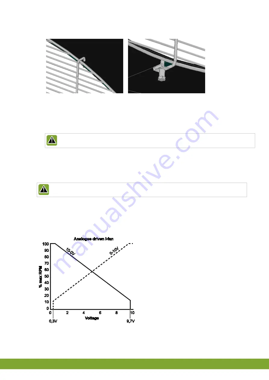
  Analogue control (0-10V;10-0V) 


Содержание I-FAN MODULAR

Страница 1: ...I FAN MODULAR G MANUAL N HANDLEIDING D ANLEITUNG F NOTICE I MANUALE GNDFI ...

Страница 2: ...roduced by Fancom For the latest information about product installation and operation please contact the customer service dept and or the technical service dept of the Fancom company concerned In spite of the care taken when compiling this manual if you should discover any errors please inform Fancom B V in writing Fancom B V PO Box 7131 5980 AC Panningen the Netherlands Copyright 2013 Fancom B V ...

Страница 3: ...2 Installing the I fan 2 2 1 Mount the I fan and manual control 2 2 2 Connect the I fan and manual control MCA 5 2 3 Install the protective screen optional 10 2 4 Test the I fan 11 3 Using the I fan 11 3 1 First use 11 3 2 Control options 11 3 3 Malfunctions 12 3 4 Maintenance 12 4 Technical specifications 13 5 EG declaration of conformity 14 ...

Страница 4: ...instructions and warnings Before installing and commissioning the I fan read the safety instructions provisions and conditions carefully This paragraph contains a number of general safety instructions In the following paragraph a number of specific safety instructions are included in the installation instruction The installation of the device and remedying of any malfunctions should be performed b...

Страница 5: ...y The direction of airflow must be from the motor to the impeller There must be sufficient free airflow available to cool the motor Most I fan units are too heavy to lift Take the necessary precautions Take the dimensions of various types of I fan into account when installing Type Ø A mm inch B mm inch Ø C mm inch D mm inch 35 440 17 3 393 15 5 362 14 3 350 13 8 40 502 19 8 398 15 7 412 16 2 350 1...

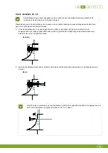
Страница 6: ...other 5 Push the linking pins in so that the tube is connected to the module If the linking pins can t be pushed in completely e g because they come in contact with the blades then place them in the half closed position Closed 6 Secure the linking pins by screwing in a screw with lock washer from inside the tube into the linking pins Drilling 50 and 56 I fan in combination with CLICK extension tub...

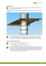
Страница 7: ... hanging eyes and accessories are available in a mounting kit Install the protective screen optional Placement of a protective screen is necessary if the I fan is within reach of animals and or people and is installed at heights less than 2 7 m above the floor The blades of the I fan may run backward due to external influences To prevent the I fan turning in the opposite direction it is necessary ...

Страница 8: ...s on the fan s 2 2 Connect the I fan and manual control MCA Before connecting turn off the power and turn it back on only after the entire installation is ready The motor thermal protection is already integrated in the I fan Do not connect more than two I fan units to one fuse Make sure that the I fan is well and properly grounded according to the guidelines Keep signal and power cables as short a...

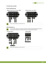
Страница 9: ...CA Analogue control and alarm MCA Alarm contact unpowered 2A 30Vac 60Vdc With manual control In order to connect the regulator s analogue output the standard connection Analogue In 3 and Gnd 4 must first be removed from the cover Connection box MCA Cover MCA Alarm contact unpowered 2A 30Vac 60Vdc ...

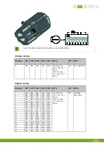
Страница 10: ...umper settings are set to overrule the digitally controlled I fan units via the I O network 1 10V To overrule the analogue control I fan units the jumper settings must be changed to 0 10V 10 0V Do this as follows 1 Replace the jumper with resistance with the jumper delivered as a standard 2 Set the jumper to the proper position Set the I O address Using the table on the following pages set an I O ...

Страница 11: ...1 DIP 2 DIP 3 DIP 4 DIP 5 DIP 6 DIP 7 DIP 8 1 OFF ON ON ON ON ON 10 0V dc 10V 0 0V 100 OFF 0 10V dc 0V 0 10V 100 ON ON 50 OFF 100 2 ON OFF ON ON ON 3 OFF OFF ON ON ON 4 ON ON OFF ON ON 5 OFF ON OFF ON ON 6 ON OFF OFF ON ON 7 OFF OFF OFF ON ON 8 ON ON ON OFF ON 9 OFF ON ON OFF ON 10 ON OFF ON OFF ON 11 OFF OFF ON OFF ON 12 ON ON OFF OFF ON 13 OFF ON OFF OFF ON 14 ON OFF OFF OFF ON 15 OFF OFF OFF OF...

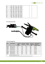
Страница 12: ...able mm2 Power draw A Leakage current mA Rated power W Noise at a distance of 2m and 7m dB IF35M I 208 240 10 3x1 1 17 4 8 231 61 50 IF40M I 208 240 10 3x1 1 43 4 8 286 64 53 IF45M I 208 240 10 3x1 1 69 4 8 346 66 55 IF50M I 208 240 10 3x1 2 32 4 8 470 67 56 IF50PI 208 240 10 3x1 3 15 4 8 683 70 59 IF56M I 208 240 10 3x1 3 03 4 8 653 71 60 IF63M I 208 240 10 3x1 3 13 4 8 672 68 57 IF80M I 208 240 ...

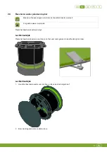
Страница 13: ...ake sure that the impeller is not turning Install the protective screen as follows Air inlet side Install the protective screen on the I fan and secure it as shown in the illustration below Air outlet side 1 Hold the protective screen up to the I fan and trace the three drill holes 2 Drill the three holes with a ø5mm bit ...

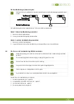
Страница 14: ... the I fan has been connected correctly 2 Check whether the I fan works optimally Do not touch any of the I fan moving parts 3 Using the I fan 3 1 First use Do not touch any of the I fan moving parts Fancom advises to leave the I fan on for about 6 hours after installation to let it run in 3 2 Control options Analogue control 0 10V 10 0V ...

Страница 15: ...ed off If the I fan no longer starts independently the I fan must be removed from power for at least 30 seconds and then be started up again Digital If I O communication is interrupted the last set value remains active Turning the power supply on and off without I O communication will activate the predefined setting of dipswitch 8 ON 50 OFF 100 see also page 7 3 4 Maintenance The I fan requires no...

Страница 16: ...ing or after the cleaning process Note that the air inlet side is always on the bottom side After cleaning the I fan it should run at 100 rpm for at least 30 minutes to remove all dampness 4 Technical specifications Housing Protection class IP66 Operating environment Operating temperature range 0 C to 40 C Storage temperature range 10 C tot 50 C Relative humidity 85 not condensing ...

Страница 17: ...ge directive 2006 95 EC according to NEN EN IEC 60335 01 2012 2 Machine directive 2006 42 EC Industrial ventilators according to NEN EN IEC 14461 2002 3 EMC directive 2004 108 EC Emission according to NEN EN IEC 61000 6 3 2007 Immunity according to NEN EN IEC 61000 6 2 2005 4 Ecodesign requirements directive 2009 125 EC according to NR 327 2011 City Panningen Date 17 7 2013 Paul Smits Managing Dir...

Страница 18: ... over productinstallatie en bediening neem contact op met de klantenservice en of technische serviceafdeling van de betreffende Fancom onderneming Mocht u onverhoopt toch een fout ontdekken dan vragen wij u vriendelijk Fancom B V hiervan schriftelijk in kennis te stellen Fancom B V Postbus 7131 5980 AC Panningen the Netherlands Copyright 2013 Fancom B V Panningen the Netherlands Alle rechten zijn ...

Страница 19: ... De I fan installeren 2 2 1 De I fan en de handbediening monteren 2 2 2 De I fan en de handbediening MCA aansluiten 5 2 3 Beschermrooster plaatsen optie 10 2 4 De I fan testen 11 3 De I fan gebruiken 11 3 1 Eerste gebruik 11 3 2 Mogelijkheden voor sturing 11 3 3 Storingen 12 3 4 Onderhoud 12 4 Technische gegevens 13 5 EG verklaring van overeenstemming 14 ...

Страница 20: ...dsinstructies en waarschuwingen Lees de veiligheidsinstructies bepalingen en voorwaarden aandachtig voordat u de I fan installeert en in gebruik neemt In deze paragraaf staan een aantal algemene veiligheidsinstructies In de volgende paragraaf staan bij de installatie instructies ook een aantal specifieke veiligheidsinstructies De installatie van het apparaat en het verhelpen van eventuele storinge...

Страница 21: ...ht moet van de motor naar de waaier stromen Er moet voldoende vrije luchtstroom aanwezig zijn voor koeling van de motor De meeste I fan units zijn te zwaar om te tillen Neem daarom de noodzakelijk voorzorgsmaatregelen Houd bij montage rekening met de afmetingen van de verschillende typen I fan Type Ø A mm inch B mm inch Ø C mm inch D mm inch 35 440 17 3 393 15 5 362 14 3 350 13 8 40 502 19 8 398 1...

Страница 22: ...en 5 Druk de koppelpennen in de openingen zodat de koker is verbonden met de module Mochten de koppelpennen niet volledig ingedrukt kunnen worden bijvoorbeeld omdat ze tegen de waaier aankomen plaats ze dan in de half gesloten stand Gesloten 6 Borg de koppelpennen door een schroef met sluitring vanuit de binnenkant van de koker in de koppelpennen te draaien Boren I fan 50 en 56 in combinatie met v...

Страница 23: ...ogen en toebehoren zijn beschikbaar in een montageset Beschermrooster plaatsen optie Het is nodig een beschermrooster te plaatsen als de I fan zich binnen bereik van mensen en of dieren bevindt en een montagehoogte van minder dan 2 7 m boven de vloer heeft Door externe invloeden kunnen de waaierbladen van de I fan in tegengestelde richting gaan draaien Om te voorkomen dat de I fan in tegengestelde...

Страница 24: ... 2 De I fan en de handbediening MCA aansluiten Schakel de spanning uit voordat u de unit aansluit en schakel deze pas in nadat volledige installatie gereed is De motorbeveiliging thermische beveiliging is reeds geïntegreerd in de I fan Sluit niet meer dan twee I fan units aan op één zekering Zorg ervoor dat de I fan volgens de voorschriften goed en degelijk geaard is Houd de signaal en voedingskab...

Страница 25: ... MCA Alarmcontact potentiaalvrij 2 A 30 Vac 60 Vdc Met handbediening Als u de analoge uitgang van de regelaar wilt aansluiten moet eerst de standaardverbinding tussen de analoge ingang 3 Analogue In en aarde 4 Ground in de deksel worden verwijderd Aansluitbox MCA Afdekkap MCA Alarmcontact potentiaalvrij 2 A 30 Vac 60 Vdc ...

Страница 26: ...ers ingesteld om de digitaal gestuurde I fan units te overbruggen via het I O net 1 10 V Voor het overbruggen van de analoog gestuurde I fan units moeten de jumperinstellingen worden gewijzigd naar 0 10 V 10 0 V Dit doet u als volgt 1 Vervang de jumper met de weerstand door de standaard meegeleverde jumper 2 Zet de jumper in de juiste stand Het I O adres instellen Stel met behulp van de tabel op d...

Страница 27: ...P 1 DIP 2 DIP 3 DIP 4 DIP 5 DIP 6 DIP 7 DIP 8 1 OFF ON ON ON ON ON 10 0 Vdc 10 V 0 0 V 100 OFF 0 10 Vdc 0 V 0 10 V 100 ON ON 50 OFF 100 2 ON OFF ON ON ON 3 OFF OFF ON ON ON 4 ON ON OFF ON ON 5 OFF ON OFF ON ON 6 ON OFF OFF ON ON 7 OFF OFF OFF ON ON 8 ON ON ON OFF ON 9 OFF ON ON OFF ON 10 ON OFF ON OFF ON 11 OFF OFF ON OFF ON 12 ON ON OFF OFF ON 13 OFF ON OFF OFF ON 14 ON OFF OFF OFF ON 15 OFF OFF ...

Страница 28: ...troomver bruik A Lekstroo m mA Nominaal vermogen W Geluidsterkte op 2 m en 7 m afstand dB IF35M I 208 240 10 3x1 1 17 4 8 231 61 50 IF40M I 208 240 10 3x1 1 43 4 8 286 64 53 IF45M I 208 240 10 3x1 1 69 4 8 346 66 55 IF50M I 208 240 10 3x1 2 32 4 8 470 67 56 IF50PI 208 240 10 3x1 3 15 4 8 683 70 59 IF56M I 208 240 10 3x1 3 03 4 8 653 71 60 IF63M I 208 240 10 3x1 3 13 4 8 672 68 57 IF80M I 208 240 1...

Страница 29: ...rt Zorg dat de waaier niet draait Plaats het beschermrooster als volgt Luchtinlaatzijde Plaats het beschermrooster op de I fan en zet het vast zoals getoond in de afbeelding hieronder Luchtuitlaatzijde 1 Houdt het beschermrooster voor de I fan en teken de drie boorgaten af 2 Boor de drie gaten met een ø5mm boor ...

Страница 30: ...en 2 Controleer of de I fan optimaal werkt Raak de bewegende onderdelen van de I fan niet aan 3 De I fan gebruiken 3 1 Eerste gebruik Raak de bewegende onderdelen van de I fan niet aan Fancom adviseert om de I fan gedurende circa 6 uur na installatie ingeschakeld te laten zodat deze kan inwerken 3 2 Mogelijkheden voor sturing Analoge sturing 0 10 V 10 0 V ...

Страница 31: ... opstart moet de I fan minimaal 30 seconden spanningsloos gemaakt worden om vervolgens weer op te starten Digitaal Bij het wegvallen van I O communicatie blijft de laatst ingestelde waarde actief Bij in en uitschakelen van de voedingsspanning zonder I O communicatie wordt de vooraf gedefinieerde instelling van dipswitch 8 aangenomen ON 50 OFF 100 zie ook pagina 7 3 4 Onderhoud De I fan vereist gee...

Страница 32: ...de I fan niet tijdens of na het schoonmaken Zorg dat de luchtinlaat altijd naar beneden is gericht Na het reinigen van de I fan moet deze minimaal 30 minuten op 100 nadraaien om alle vocht zo snel mogelijk af te voeren 4 Technische gegevens Behuizing Beschermingsklasse IP66 Bedrijfsomgeving Bereik bedrijfstemperatuur 0 C tot 40 C Bereik opslagtemperatuur 10 C tot 50 C Relatieve vochtigheid 85 niet...

Страница 33: ...1 Laagspanningsrichtlijn 2006 95 EC conform NEN EN IEC 60335 01 2012 2 Machinerichtlijn 2006 42 EC Industriële ventilatoren volgens NEN EN IEC 14461 2002 3 EMC richtlijn 2004 108 EG Emissienorm conform NEN EN IEC 61000 6 3 2007 Immuniteitsnorm conform NEN EN IEC 61000 6 2 2005 4 Ecodesign richtlijn 2009 125 EG conform nr 327 2011 Stad Panningen Datum 15 7 2013 Paul Smits Managing Director ...

Страница 34: ...d Bedienung nehmen Sie bitte Kontakt mit dem Kundendienst und oder dem technischen Service der zuständigen Fancom Niederlassung auf Sollten Sie ungeachtet der Sorgfalt mit der die Anleitung verfasst worden ist einen Fehler darin entdecken bitten wir Sie Fancom B V darüber schriftlich zu informieren Fancom B V PO Box 7131 5980 AC Panningen The Netherlands Copyright 2013 Fancom B V Panningen The Net...

Страница 35: ...llation des I fan 2 2 1 Den I fan und die Handbedienung montieren 2 2 2 Den I fan und die Handbedienung MCA anschließen 5 2 3 Einbau des Schutzgitters optional 10 2 4 Überprüfung des I fan 12 3 Verwendung des I fan 12 3 1 Erstinbetriebnahme 12 3 2 Steuerungsoptionen 12 3 3 Störungen 13 3 4 Wartung 13 4 Technische Daten 14 5 EG Konformitätserklärung 15 ...

Страница 36: ... Sicherheitshinweise Bestimmungen und Auflagen müssen vor der Installation und Inbetriebnahme des I fan aufmerksam gelesen werden Dieser Abschnitt enthält zahlreiche allgemeine Sicherheitshinweise Im nachfolgenden Abschnitt sind in den Installationsanweisungen eine Reihe spezieller Sicherheitsvorschriften enthalten Die Installation und die Behebung eventueller Störungen müssen den geltenden Normen...

Страница 37: ...trom muss sich vom Motor in Richtung Flügelrad bewegen Es muss ein ausreichend großer freier Luftstrom vorhanden sein um den Motor zu kühlen Die meisten I fan Einheiten sind zu schwer zum Anheben Ergreifen Sie die erforderlichen Vorsichtsmaßnahmen Beachten Sie beim Einbau die Abmessungen der verschiedenen I fan Typen Typ Ø A mm Zoll B mm Zoll Ø C mm Zoll D mm Zoll 0 34 440 17 3 393 15 5 362 14 3 3...

Страница 38: ...ch welche die Sicherungsstifte gesteckt werden genau gegenüber voneinander liegen 5 Die Sicherungsstifte eindrücken sodass das Rohr mit dem Modul verbunden ist Falls die Sicherungsstifte nicht vollständig eingedrückt werden können z B weil sie die Schaufeln berühren diese in halb geschlossener Position belassen Geschlossen 6 Die Sicherungsstifte sichern indem eine Schraube mit Federring von der In...

Страница 39: ...en Sie mindestens 4 für die Befestigung auf der Dach Konstruktion verwenden Das Seil die Kette am Rohrmodul und an der Dach Konstruktion befestigen Sicherstellen dass die Seile Ketten einander kreuzen Das Seil die Kette kann eventuell nicht direkt durch die hängende Öse des Rohrmoduls geführt werden Fancom empfiehlt Aufhängeösen aus Stahl durch die Aufhängeösen des Rohrmoduls zu führen und dann da...

Страница 40: ...ndbedienung optional Nachstehend ist ein Beispiel aufgeführt wo die Anschlussdose n und die Handbedienung eingebaut werden können Die Handbedienung kann an 1 oder mehrere Ventilatoren maximal 3 angeschlossen werden Option 1 Anschluss der lokalen Handbedienung 1 Montage der lokalen Handbedienung 2 Austausch der standardmäßigen Anschlussdose Option 2 Anschluss der zentralen Handbedienung 1 Montage d...

Страница 41: ... der Steckbrücken am MCA kontrollieren siehe seite 7 3 Die I O Adresse einstellen siehe seite 8 4 Die Stromversorgung anschließen siehe seite 10 Anschluss der Bedieneinrichtung Ohne Handbedienung Digitale Steuerung über I O Netz und Alarm MCA Analoge Steuerung und Alarm MCA Alarmkontakt stromlos 2 A 30 V AC 60 V DC Mit Handbedienung Für den Anschluss des Analogausgangs des Reglers müssen zuerst de...

Страница 42: ...tilator en Die Einstellungen der Steckbrücken am MCA kontrollieren Standardmäßig sind die Steckbrücken so eingestellt dass sie die digital gesteuerten I fan Einheiten über das I O Netz 1 10 V außer Kraft setzen Um die analog gesteuerten I fan Einheiten außer Kraft zu setzen müssen die Einstellungen der Steckbrücken auf 0 10 V 10 0 V geändert werden Dies geschieht wie folgt 1 Tauschen Sie die Steck...

Страница 43: ...den Seiten mit den DIP Schaltern eine I O Adresse am Motor des rgeg g sdf gprod ein In einem I O Netz müssen alle I fan Einheiten eine eindeutige Adresse haben Analoge Steuerung I O Adress e DIP 1 DIP 2 DIP 3 DIP 4 DIP 5 DIP 6 DIP 7 DIP 8 0 EIN EIN EIN EIN EIN EIN 10 0 V DC 10 V 0 0 V 100 AUS 0 10 V DC 0 V 0 10 V 100 EIN Entfällt EIN AUS ...

Страница 44: ... AUS EIN 9 AUS EIN EIN AUS EIN 10 EIN AUS EIN AUS EIN 11 AUS AUS EIN AUS EIN 12 EIN EIN AUS AUS EIN 13 AUS EIN AUS AUS EIN 14 EIN AUS AUS AUS EIN 15 AUS AUS AUS AUS EIN 16 EIN EIN EIN EIN AUS 17 AUS EIN EIN EIN AUS 18 EIN AUS EIN EIN AUS 19 AUS AUS EIN EIN AUS 20 EIN EIN AUS EIN AUS 21 AUS EIN AUS EIN AUS 22 EIN AUS AUS EIN AUS 23 AUS AUS AUS EIN AUS 24 EIN EIN EIN AUS AUS 25 AUS EIN EIN AUS AUS 2...

Страница 45: ...208 240 10 3x1 2 32 4 8 470 67 56 IF50PI 208 240 10 3x1 3 15 4 8 683 70 59 IF56M I 208 240 10 3x1 3 03 4 8 653 71 60 IF63M I 208 240 10 3x1 3 13 4 8 672 68 57 IF80M I 208 240 10 3x1 3 97 8 5 911 69 58 IF92I 208 240 10 3x1 4 03 8 5 908 67 56 Bei Nennspannung mit 50 Pa Berechnete Werte bei einem Winkel von 45 mit der I fan Welle bei 0 Pa 2 3 Einbau des Schutzgitters optional Vor der Montage des Schu...

Страница 46: ...folgenden Abbildung gezeigt sichern Abluftseite 1 Halten Sie das Schutzgitter auf den I fan und suchen Sie die drei Bohrlöcher 2 Bohren Sie die drei Löcher mit einem 5 mm Bohrer 3 Setzen Sie das Schutzgitter auf den I fan und befestigen Sie es mit einer Schraube der Abmessung M5 x 30 ...

Страница 47: ...l funktioniert Berühren Sie keine beweglichen Teile des I fan 3 Verwendung des I fan 3 1 Erstinbetriebnahme Berühren Sie keine beweglichen Teile des I fan Fancom empfiehlt den I fan für ca 6 Stunden nach der Installation eingeschaltet zu lassen damit er sich einlaufen kann 3 2 Steuerungsoptionen Analoge Steuerung 0 10 V 10 0 V ...

Страница 48: ...fuhr zum Ventilator mindestens 30 Sekunden getrennt und dann wieder gestartet werden Digital Wenn die I O Kommunikation unterbrochen ist bleibt der letzte eingestellte Wert aktiv Durch das Ein und Ausschalten der Stromversorgung ohne I O Kommunikation wird die vorgegebene Einstellung von DIP Schalter 8 aktiviert ON 50 OFF 100 siehe auch seite 8 3 4 Wartung Eine spezielle Wartung dieses I fan ist n...

Страница 49: ... Sie den I fan nicht während oder nach dem Reinigungsvorgang Beachten Sie dass sich die Lufteinlassseite immer an der Unterseite befindet Nach der Reinigung des I fan sollte er sich mindestens 30 Minuten mit 100 Leistung drehen um sämtliche Feuchtigkeit zu beseitigen 4 Technische Daten Gehäuse Schutzklasse IP66 Umgebungsklima Betriebstemperaturbereich 0 bis 40 C Lagertemperaturbereich 10 C bis 50 ...

Страница 50: ... 1 Niederspannungsrichtlinie 2006 95 EG gemäß NEN EN IEC 60335 01 2012 2 Maschinenrichtlinie 2006 42 EG Industrielüfter gemäß NEN EN IEC 14461 2002 3 EMV Richtlinie 2004 108 EG Emissionen gemäß NEN EN IEC 61000 6 3 2007 Immunität gemäß NEN EN IEC 61000 6 2 2005 4 Ökodesign Richtlinie 2009 125 EG Gemäß NR 327 2011 Stadt Panningen Datum 15 7 2013 Paul Smits Managing Director ...

Страница 51: ...Fancom Pour connaître les informations les plus récentes relatives à l utilisation et à l installation du produit contactez le service client ou technique de la société Fancom en question Bien que toutes les mesures aient été prises lors de la compilation de ce manuel veuillez informer Fancom B V par écrit si vous rencontrez une erreur Fancom B V PO Box 7131 5980 AC Panningen The Netherlands Copyr...

Страница 52: ...I fan 2 2 1 Montage du I fan et de la commande manuelle 2 2 2 Branchement du I fan et de la commande manuelle MCA 5 2 3 Installation de la grille de protection facultative 10 2 4 Test du I fan 11 3 Utilisation du I fan 11 3 1 Première utilisation 11 3 2 Options de commande 11 3 3 Dysfonctionnements 12 3 4 Entretien 12 4 Spécifications techniques 13 5 Certificat européen de conformité 14 ...

Страница 53: ...rité et avertissements Avant d installer et de mettre en service la solution I fan lisez attentivement les instructions consignes et précautions à suivre Ce paragraphe comprend un certain nombre de consignes de sécurité générales Dans le paragraphe suivant les instructions d installation comprennent un certain nombre de consignes générales de sécurité L installation de l appareil et la correction ...

Страница 54: ...isante L air doit circuler du moteur vers le ventilateur Le débit doit être suffisant pour refroidir le moteur La plupart des unités I fan sont trop lourdes pour être soulevées Prenez toutes les précautions nécessaires Tenez compte des dimensions des différents types de I fan lors de l installation Type Ø A mm pouce B mm pouce Ø C mm pouce D mm pouce 35 440 17 3 393 15 5 362 14 3 350 13 8 40 502 1...

Страница 55: ...Enfoncez les goujons de manière à ce que le tube soit bien fixé au module S il n est pas possible d enfoncer complètement les goujons par exemple parce qu ils sont entrés en contact avec les pales placez les en position demi fermée Fermé 6 Fixez les goujons en y introduisant une vis et une rondelle d arrêt à partir de l intérieur du tube Perçage Les I fan 50 et 56 combinés à des tubes de rallonge ...

Страница 56: ... chaîne Ces yeux de suspension et accessoires sont disponibles dans un kit de montage Installation de la grille de protection facultative Si nécessaire installation d une grille de protection dans le I fan est à portée des animaux et ou personnes et est installé à une hauteur de moins de 2 7 m au dessus du sol Les pales du I fan peuvent tourner à l envers sous l effet d une influence extérieure Po...

Страница 57: ...Branchement du I fan et de la commande manuelle MCA Avant d effectuer le branchement coupez le courant et ne le rétablissez qu une fois toute l installation terminée La protection du moteur thermique est déjà intégrée dans le I fan Ne raccordez pas plus de deux unités I fan à un même fusible Vérifiez que le I fan est bien raccordé à la terre conformément aux directives Les câbles de transmission d...

Страница 58: ...Commande analogique et alarme MCA Contact d alarme non alimenté 2 A 30 Vca 60 Vcc Avec commande manuelle Pour brancher la sortie analogique du régulateur vous devez d abord retirer les prises analogiques In 3 et Gnd 4 standard Boîtier de raccordement MCA Capot MCA Contact d alarme non alimenté 2 A 30 Vca 60 Vcc ...

Страница 59: ... cavalier est prioritaire sur les unités de I fan à commande numérique via le réseau d E S 1 10 V Pour contourner les unités de I fan à commande analogique le cavalier doit être reconfiguré en 0 10 V 10 0 V Pour ce faire procédez comme suit 1 Remplacez le cavalier doté d une résistance par le cavalier fourni en standard 2 Placez le cavalier sur la position adéquate Définition de l adresse d E S Dé...

Страница 60: ...sse d E S DIP 1 DIP 2 DIP 3 DIP 4 DIP 5 DIP 6 DIP 7 DIP 8 1 OFF ON ON ON ON ON 10 0 V CC 10 V 0 0 V 100 OFF 0 10 V CC 0 V 0 10 V 100 ON ON 50 OFF 100 2 ON OFF ON ON ON 3 OFF OFF ON ON ON 4 ON ON OFF ON ON 5 OFF ON OFF ON ON 6 ON OFF OFF ON ON 7 OFF OFF OFF ON ON 8 ON ON ON OFF ON 9 OFF ON ON OFF ON 10 ON OFF ON OFF ON 11 OFF OFF ON OFF ON 12 ON ON OFF OFF ON 13 OFF ON OFF OFF ON 14 ON OFF OFF OFF ...

Страница 61: ...rélèveme nt de courant A Fuite de courant mA Puissance nominale W Bruit à une distance de 2 m et de 7 m dB IF35M I 208 240 10 3 x 1 1 17 4 8 231 61 50 IF40M I 208 240 10 3 x 1 1 43 4 8 286 64 53 IF45M I 208 240 10 3 x 1 1 69 4 8 346 66 55 IF50M I 208 240 10 3 x 1 2 32 4 8 470 67 56 IF50PI 208 240 10 3 x 1 3 15 4 8 683 70 59 IF56M I 208 240 10 3 x 1 3 03 4 8 653 71 60 IF63M I 208 240 10 3 x 1 3 13 ...

Страница 62: ...ntilateur ne fonctionne pas Installez la grille de protection comme suit Côté admission d air Installez la grille de protection sur le I fan et fixez la comme sur l illustration ci dessous Côté sortie d air 1 Tenez la grille de protection devant le I fan et marquez l emplacement des trois trous à percer 2 Percez les trois trous avec une mèche de 5 mm de diamètre ...

Страница 63: ...ent branché 2 Vérifiez que le I fan fonctionne correctement Ne touchez aucune partie mobile du I fan 3 Utilisation du I fan 3 1 Première utilisation Ne touchez aucune partie mobile du I fan Fancom vous conseille de laisser le I fan sous tension pendant 6 heures environ après l installation 3 2 Options de commande Commande analogique 0 10 V 10 0 V ...

Страница 64: ...larme est coupé Si le I fan ne démarre plus indépendamment le I fan doit être débranché du secteur au moins 30 secondes avant d être remis en marche Numérique Si la communication E S est interrompue c est la dernière valeur spécifiée qui reste active Couper l alimentation et la rétablir sans communication E S active le réglage prédéfini du commutateur DIP 8 ON 50 OFF 100 voir aussi page 7 3 4 Entr...

Страница 65: ... fan pendant ou après le processus de nettoyage Veuillez noter que l admission d air est toujours située au niveau de la base Après avoir nettoyé le I fan faites le tourner à 100 de sa vitesse pendant au moins 30 minutes pour évacuer toute trace d humidité 4 Spécifications techniques Boîtier Classe de protection IP66 Environnement de fonctionnement Températures de fonctionnement 0 à 40 C Températu...

Страница 66: ... la norme NEN EN IEC 60335 01 2012 2 Directive sur les machines 2006 42 CE Ventilateurs industriels conformément à la norme NEN EN 14461 2002 3 Directive sur les émissions électromagnétiques 2004 108 CE Émissions conformément à la norme NEN EN 61000 6 3 2007 Immunité conformément à la norme NEN EN 61000 6 2 2005 4 Exigences d éco conception de la directive 2009 125 CE conformément à la norme NR 32...

Страница 67: ...rnate relativamente all installazione del prodotto e alla sua conduzione si prega di contattare il servizio assistenza clienti e o il dipartimento di assistenza tecnica dell azienda Fancom Se nonostante la cura con cui questo manuale è stato redatto venissero comunque riscontrati degli errori si prega di segnalarlo per iscritto a Fancom B V Fancom B V PO Box 7131 5980 AC Panningen the Netherlands ...

Страница 68: ...I fan 2 2 1 Montare il I fan e il controllo manuale 2 2 2 Collegare il I fan e il controllo manuale MCA 5 2 3 Installare la griglia di protezione opzionale 10 2 4 Collaudare il I fan 12 3 Utilizzo del I fan 12 3 1 Primo utilizzo 12 3 2 Opzioni di controllo 12 3 3 Malfunzionamenti 13 3 4 Manutenzione 13 4 Specifiche tecniche 14 5 Dichiarazione di conformità EG 15 ...

Страница 69: ...di installare e mettere in servizio il I fan leggere con attenzione le istruzioni di sicurezza le disposizioni e le condizioni Questo paragrafo contiene alcune istruzioni di sicurezza di carattere generale Nel paragrafo seguente sono incluse alcune istruzioni di sicurezza specifiche per la fase d installazione L installazione del dispositivo e la riparazione di eventuali mal funzionamenti devono e...

Страница 70: ...ione del flusso d aria deve essere dal motore al rotore Ci deve essere un flusso di aria sufficiente a raffreddare il motore La maggior parte delle unità I fan sono troppo pesanti da sollevare Prendere le necessarie precauzioni Nel corso dell installazione tenere in considerazione le dimensioni dei vari tipi di I fan Tipo Ø A mm pollici B mm pollici Ø C mm pollici D mm pollici 35 440 17 3 393 15 5...

Страница 71: ...re attraverso le quali far passare i perni di collegamento sono collegamento opposte uno dall altra 5 Spingere i perni di collegamento in modo che il tubo risulti collegato al modulo Se i perni di collegamento non possono essere spinti fino in fondo ad esempio perché vengono in contatto con le pale inserirli nella posizione semichiusa Chiuso 6 Fissare i perni di collegamento avvitando una vite con...

Страница 72: ...ario utilizzarne almeno 4 per il fissaggio alla struttura tetto Collegare il cavo catena al modulo tubo ed alla struttura tetto Assicurarsi che i cavi catene si incrocino tra loro Il cavo catena non può passare direttamente attraverso gli occhielli di sospensione del modulo Fancom consiglia di far passare le viti ad occhiello in metallo attraverso le fessure di sospensione del modulo e successivam...

Страница 73: ...uito è riportato un esempio di posizionamento della e scatole di giunzione e dei controlli manuali Il controllo manuale può essere collegato a 1 o più ventilatori massimo 3 Opzione 1 Connessione del controllo manuale locale 1 Montare il controllo manuale locale 2 Sostituire la scatola di giunzione fornita nella dotazione standard Opzione 2 Connessione del controllo manuale centralizzato 1 Montare ...

Страница 74: ... 3 Impostare l indirizzo I O vedi pagina 8 4 Collegare l alimentazione vedi pagina 10 Collegare il controllo Senza controllo manuale Controllo digitale via rete I O e allarme MCA Controllo analogico e allarme MCA Contatto allarme non alimentato 2 A 30 V CA 60 V CC Con controllo manuale Per collegare l uscita analogica del regolatore è necessario scollegare prima la connessione standard Ingresso an...

Страница 75: ...ra 4 alla scatola di giunzione sul i ventilatori Controllare le impostazioni dei ponticelli sull MCA Come impostazione predefinita i ponticelli sono impostati per prevalere sui I fan con controllo digitale via rete I O 1 10 V Per prevalere sui I fan con controllo analogico i ponticelli devono essere impostati su 0 10 V 10 0 V Procedere come indicato di seguito 1 Sostituire il ponticello con la res...

Страница 76: ...llo nella posizione corretta Impostare l indirizzo I O Utilizzando la tabella nelle pagine seguenti impostare un indirizzo I O con i dip switch sul motore del rgeg g sdf gprod In una rete I O ogni I fan deve avere un indirizzo univoco ...

Страница 77: ...N ON ON 4 ON ON OFF ON ON 5 OFF ON OFF ON ON 6 ON OFF OFF ON ON 7 OFF OFF OFF ON ON 8 ON ON ON OFF ON 9 OFF ON ON OFF ON 10 ON OFF ON OFF ON 11 OFF OFF ON OFF ON 12 ON ON OFF OFF ON 13 OFF ON OFF OFF ON 14 ON OFF OFF OFF ON 15 OFF OFF OFF OFF ON 16 ON ON ON ON OFF 17 OFF ON ON ON OFF 18 ON OFF ON ON OFF 19 OFF OFF ON ON OFF 20 ON ON OFF ON OFF 21 OFF ON OFF ON OFF 22 ON OFF OFF ON OFF 23 OFF OFF O...

Страница 78: ... 32 4 8 470 67 56 IF50PI 208 240 10 3x1 3 15 4 8 683 70 59 IF56M I 208 240 10 3x1 3 03 4 8 653 71 60 IF63M I 208 240 10 3x1 3 13 4 8 672 68 57 IF80M I 208 240 10 3x1 3 97 8 5 911 69 58 IF92I 208 240 10 3x1 4 03 8 5 908 67 56 Alla tensione nominale di 50 Pa Valori calcolati ad un angolo di 45 con l albero del I fan a 0 Pa 2 3 Installare la griglia di protezione opzionale Interrompere l alimentazion...

Страница 79: ... fan e fissarla come mostrato nell illustrazione seguente Lato uscita aria 1 Tenere la griglia di protezione sul I fan e contrassegnare i tre fori 2 Praticare i tre fori con una punta ø 5 mm 3 Posizionare la griglia di protezione sul I fan e fissarla con un bullone M5 x 30 ...

Страница 80: ...unziona in modo ottimale Non toccare parti in movimento del I fan 3 Utilizzo del I fan 3 1 Primo utilizzo Non toccare parti in movimento del I fan Fancom raccomanda di lasciare il I fan acceso per circa 6 ore dopo l installazione per svolgere il corretto rodaggio 3 2 Opzioni di controllo Controllo analogico 0 10 V 10 0 V ...

Страница 81: ...si avvia autonomamente è necessario interrompere l alimentazione al I fan per almeno 30 secondi prima di riavviarlo Digitale Se la comunicazione I O viene interrotta l ultimo valore impostato rimane attivo Accendere e spegnere l alimentatore senza comunicazione I O causa l attivazione dell impostazione predefinita del dip switch 8 ON 50 OFF 100 vedi anche pagina 8 3 4 Manutenzione Il I fan non nec...

Страница 82: ...ante la procedura di pulizia Tenere presente che l ingresso dell aria è sempre sul lato inferiore Dopo la pulizia il I fan dovrebbe funzionare al 100 rpm per almeno 30 minuti per rimuovere completamente l umidità 4 Specifiche tecniche Custodia Classe di protezione IP66 Ambiente operativo Intervallo della temperatura di esercizio da 0 C a 40 C Intervallo della temperatura di stoccaggio da 10 C a 50...

Страница 83: ...i della 1 Direttiva bassa tensione 2006 95 CE secondo NEN EN IEC 60335 01 2012 2 Direttiva macchine 2006 42 CE Ventilatori industriali secondo NEN EN IEC 14461 2002 3 Direttiva EMC 2004 108 CE Emissioni secondo NEN EN IEC 61000 6 3 2007 Immunità secondo NEN EN IEC 61000 6 2 2005 4 Direttiva Ecodesign 2009 125 CE secondo NR 327 2011 Località Panningen Data 15 7 2013 Paul Smits Managing Director ...

Отзывы: