background image

10

10. Connect power and the fan as electrical wiring diagram. 

IMPORTANT: The fan must be earthed! Double pole disconnection switch and wall switch 
must be connected.

11. Place the canopy over the bracket, align the canopy holes with the screws and tighten.
Align decorative holes with the screws and twist it to secure it onto the canopy.

12. For the light model - hold the diffuser to the 
bottom of the motor and rotate clockwise until 
it locks into place.

Содержание Breeze AC

Страница 1: ...Breeze AC AC Installation Manual...

Страница 2: ...eiling Please note that insufficient clearance distances might cause wobbling and the bigger this clearance is the better the airflow from your fan will be 8 This product can be installed in a positio...

Страница 3: ...important safeguards and instructions given in this manual are not meant to cover all possible conditions and situations that may occur It must be understood that common sense caution and care are fac...

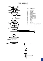
Страница 4: ...joint 3 Downrod 4 Hanging bracket 5 Canopy 6 Decorative ring 7 Coupling cover 8 Downrod holder 9 Motor housing 10 Motor 11 Blades 12 Screws pack balancing kit 13 Wall control WITHOUT LIGHT 1 2 3 4 5...

Страница 5: ...List of Components 1 Earth wire 2 Ball joint 3 Downrod 4 Hanging bracket 5 Canopy 6 Decorative ring 7 Coupling cover 8 Downrod holder 9 Motor housing 10 Motor 11 Blades 12 Light 13 Diffuser 14 Screws...

Страница 6: ...be 3 This product can be installed in a position where it is covered or enclosed al fresco areas and there is a minimum clearance of 1 50 m from the blade tip to all edges of the roof or positions wh...

Страница 7: ...WIRING DIAGRAM WITHOUT LIGHT N L To motor L N L N Double pole disconnection switch or 2 pin plug WIRING DIAGRAM WITH LIGHT N L To motor L To light L N L N Double pole disconnection switch or 2 pin plu...

Страница 8: ...Remove side screws from extension rod Put the motor housing through the extension down rod and secure with 3 screws 3 For models with light Take off 3 screws on light kit fixing plate Align the light...

Страница 9: ...holes aligned with the base of the motor bush and downrod CAUTION DO NOT force the cross pin gently wiggle and rotate it until it glides through both holes Replace the cotter pin on the other side of...

Страница 10: ...Place hanging ball into the bracket 6 Put the decorative ring and canopy through the down rod 7 Place the hanging ball on top of the down rod and secure it with the ball pin and two screws CAUTION sec...

Страница 11: ...itch and wall switch must be connected 11 Place the canopy over the bracket align the canopy holes with the screws and tighten Align decorative holes with the screws and twist it to secure it onto the...

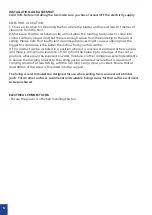
Страница 12: ...hock The motor has a permanently lubricated ball bearing and as such is maintenance free NOISE The manufacturer warranty covers actual faults that may develop but NOT minor complaints e g motor operat...

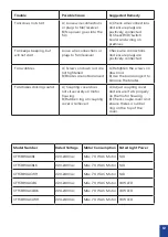
Страница 13: ...screws on down rod B Use the balancing kit to balance the blades Fan makes clicking sound A Coupling cover does not sit securely on motor housing B Rubber ring on coupling cover is removed A Adjust c...

Страница 14: ......

Отзывы: