background image

WARNING – SERVICING TO BE CARRIED OUT ONLY BY AN AUTHORISED PERSON

Disconnect from electricity before servicing. Check appliance is safe when you have finished.

32

2  Hotplate

2.1  To Remove the Hotplate 

DISCONNECT FROM THE ELECTRICITY SUPPLY.
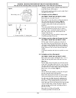
Remove the pan supports and burner heads. Remove 

the screws holding the hotplate burners to the hotplate.
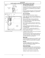
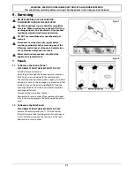
Remove the 6 screws holding the hotplate tray to the 

cooker (Fig.9-2).
Taking care not to damage the burner electrodes, 

carefully lift the hotplate. From underneath, disconnect 

the earth lead at the right-hand rear from the rear cross 

member and withdraw the hotplate.
Reassemble in reverse order, making sure that you 

reconnect the leads. Take care not to damage the 

burner ignition electrodes.
IMPORTANT: 

Make sure you replace the rear earthing 

leads when refitting the fixing screws as they form 

part of the cooker earthing.

Check for correct burner operation.

2.2  To Replace the Hotplate Control Taps

DISCONNECT FROM THE ELECTRICITY SUPPLY.

n

n

BEFORE SERVICING ANY GAS CARRYING 

COMPONENTS, TURN OFF THE GAS SUPPLY.
Remove the control panel and hotplate (see 1.1 & 2.1). 

Unplug the FSD lead from the rear of the tap. Undo the 

compression fitting at the rear of the tap and remove 

the fixings that secure the tap to the gas rail. Disconnect 

the ignition switch wiring.
Remove the tap. Remove and discard the gasket seal. Fit 

the new gasket seal to the replacement tap. Reassemble 

in reverse order. Check that the appliance is gas sound. 

Verify the hotplate ignition.

2.3  To Change a Hotplate Burner Injector

Remove the burner cap and head. Remove the old jet. 
Fit the new injector. Reassemble in reverse order. Check 

the appliance is gas sound.

2.4  To Replace a Hotplate Burner Electrode

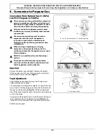
Lift off pan supports and remove the burner cap. 

Remove the screw holding the electrode. Pull the 

electrode vertically up sufficiently to grip the lead 

between thumb and forefinger. 
Pull off the electrode, but keep hold of the lead. Fit 

the new electrode to the lead. Fix the electrode in the 

burner with screw. Replace the burner cap. 
Check the burner ignition. Replace the pan supports.

2.5  To Replace a Hotplate Burner

Remove the hotplate tray (see 2.1). The burners (except 

the right-hand wok burner) are mounted on support 

struts. For these burners, disconnect the burner feed 

pipes at the burner. Remove the screws at the front 

and rear holding the support struts. Lift the strut and 

burners clear. 

The burners are fixed to the support struts with 2 

screws. Remove the appropriate burner and fit the new 

one. 
Reassemble in reverse order. Check that the burner 

operation is satisfactory.


Right-hand Wok Burner

Disconnect the burner feed pipes at the burner. Fit the 

new one and reassemble in reverse order. Check the 

burner operation.

3  Control Panel

3.1  To Replace the Ignition or light Switch

DISCONNECT FROM THE ELECTRICITY SUPPLY.
Remove the control panel (see 1.1).
Note: The old switch may be destroyed during removal. 

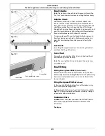
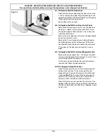
Remove the old switch from its bezel by gripping the 

switch body behind the control panel and twisting 

sharply. Remove the switch bezel by folding back the 

locking wings and pushing forward.
To fit the new bezel to the control panel, first line up the 

raised key on its body with the cut-out in the control 

panel and push it in from the front. 
Assemble the new switch to the bezel by lining up the 

key sections and pushing home. Fit the new button by 

pushing in from the front. 
Replace the control panel in reverse order and test for 

correct operation.

3.2  To Replace the Clock

DISCONNECT FROM THE ELECTRICITY SUPPLY.
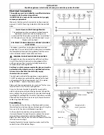
Remove the control panel (see 1.1). Pull off the timer 

control buttons.
Undo the timer fixing screws and remove the timer 

mounting bracket assembly from the control panel. 
Remove the timer from its mounting bracket by 

depressing the plastic lugs on the timer case, and at the 

same time pulling the unit forward.
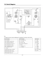
Reassemble in reverse order. When replacing the leads, 

refer to the wiring diagram. Check the operation of the 

timer.

3.3  To Change the Ignition Generator

DISCONNECT FROM THE ELECTRICITY SUPPLY.
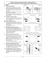
Pull the cooker forwards to gain access to the cover box 

at the rear of the cooker. Remove the screws securing 

the cover and lift clear. Pull off all the leads to the 

generator noting their positions. Slacken the 2 screws 

holding generator to cooker and remove the generator.
Fit the new generator to the cooker and replace the 

leads. Refer to the wiring diagram and reassemble in 

reverse order. Check ignition performance.

Содержание Kitchener 90

Страница 1: ...90 Dual Fuel User Guide Installation Instructions U110138 03 Australia ArtNo 000 0012 Professional logo Kitchener...

Страница 2: ...s 17 The Tall Oven 17 Cleaning Table 18 6 Troubleshooting 19 7 Installation 21 Service and Spares 21 Dear Installer 22 Provision of Ventilation 22 Location of Cooker 22 Conversion 22 Positioning the C...

Страница 3: ...se naked flames DO turn off the gas at the meter or cylinder DO open doors and windows to get rid of the gas DO keep people away from the area affected Call your gas supplier Ventilation n n CAUTION T...

Страница 4: ...hould be only one third full of fat Filling the pan too full of fat can cause spill over when food is added If you use a combination of oils or fats in frying stir them together before heating or as t...

Страница 5: ...the flow of gas if the flame goes out When the igniter button is pressed in sparks will be made at every burner this is normal Do not attempt to disassemble or clean around any burner while another bu...

Страница 6: ...ports You should also avoid using unstable and misshapen pans that may tilt easily and pans with a very small base diameter e g milk pans single egg poachers Fig 2 7 The minimum recommended pan diamet...

Страница 7: ...dle surface is non stick and metal cooking utensils e g spatulas will damage the surface Use heat resistant plastic or wooden utensils n n DO NOT put it crossways it will not fit properly and will be...

Страница 8: ...lockwise The neon indicator light by the grill control will come on For best results leave the grill pan in the grill chamber and preheat the appropriate part s of the grill for two minutes The grill...

Страница 9: ...nded cooking temperatures for a fan oven are generally lower than a conventional oven Note Please remember that all cookers vary so temperatures in your new ovens may differ to those in your previous...

Страница 10: ...tting to keep an eye on the time of day or leave it in the minute minder position as the time ticks down To stop the beeper when it sounds turn the Adjusting knob counter clockwise The cook period whi...

Страница 11: ...ked and will not come on To Activate the Key Lock Make sure that the clock is in manual mode and cancel any active programs Turn and hold the Timer knob to the clock symbol for about 8 seconds On appe...

Страница 12: ...u set the clock you must have two numbers clearly in mind the cook period and the stop time Note You cannot set a start time directly this is set automatically by setting the cook period and the stop...

Страница 13: ...and OF will now show on the display Fig 2 45 Release the buttons The programmable oven is now locked as confirmed by the display showing the time of day alongside the key symbol Fig 2 46 To Turn Off t...

Страница 14: ...en the door is open The maximum weight that can be held by the Handyrack is 5 5kg 12lb It should only be used with the supplied roasting tin which is designed to fit the Handyrack Any other vessel cou...

Страница 15: ...ing trays with food cooking on them should be placed level with the front edge of the oven s wire shelves Other containers should be placed centrally Keep all trays and containers away from the back o...

Страница 16: ...utes 20 30 minutes on a preheated tray 35 45 minutes 10 20 minutes according to size 20 40 minutes according to size 2 3 hours 45 60 minutes 40 45 minutes 2 to 3 hours 20 30 minutes Conventional Oven...

Страница 17: ...burner can also be taken apart for cleaning When reassembling the wok burner Fig 5 2 turn over the large base ring and find the D shaped area Fig 5 3 Turn the head until the D matches the one on the b...

Страница 18: ...e rail with one hand and with the other hand lift the frame up and out of the side clips Fig 5 7 For safety push the side rails back into the grill chamber If you need to remove the side rails to allo...

Страница 19: ...ing but helps to reduce the amount of manual cleaning needed These panels work better above 200 C If you do most of your cooking below this temperature occasionally remove the panels and wipe with a l...

Страница 20: ...ides and plinth Painted surface Hot soapy water soft cloth Splashback rear grille Enamel or stainless steel Hot soapy water soft cloth Cream cleaner with care if necessary Control panel Paint enamel o...

Страница 21: ...nstaller 6 Troubleshooting Power failure In the event of a failure in the electrical supply remember to reset the clock to make sure that the timed oven continues to operate Food is cooking too slowly...

Страница 22: ...o protect your fingers with a glove in case the bulb should shatter Screw in the new bulb screw back the bulb cover Turn on the circuit breaker and check that the bulb now lights The oven door is misa...

Страница 23: ...Please Note If your appliance is outside the 12 month warranty period our service provider may charge for this visit If you request an engineer to visit and the fault is not the responsibility of the...

Страница 24: ...elevant statutory regulations n n WARNING Where this appliance is installed in a marine craft caravan or mobile home it shall NOT be used as a space heater Provision of Ventilation This appliance is n...

Страница 25: ...Steel tape measure 5 Cross head screwdriver 6 Flat head screwdriver 7 4mm 3mm Allen keys 8 Spirit level 9 Pencil 10 Adjustable spanner 11 13mm spanner or socket wrench 12 Screws for fitting the restra...

Страница 26: ...th a minimum thickness of 0 4mm to a height C of not less than 150mm above the hotplate should satisfy this requirement 3 Side Clearances Measurement D E Where D the distance from the periphery of the...

Страница 27: ...rear rollers can be adjusted to level the cooker To adjust the height of the rear of the cooker use a 13mm spanner or socket wrench to turn the hexagonal adjusting nuts at the front bottom corners of...

Страница 28: ...f valve The hose should be fitted so that both inlet and outlet connections are vertical so that the hose hangs downwards in a U shape Fig 7 10 A flexible connection is supplied with the cooker If it...

Страница 29: ...erformed with particular care by a qualified technician who must also check that the electricity supply characteristics are correct The total electrical load of the appliance is approximately 7 4kW Th...

Страница 30: ...d check that the grill heats up Oven Check Turn on the oven and check that it starts to heat up Check that the oven lights are working Note The oven light bulb is not included in the guarantee Turn of...

Страница 31: ...r unauthorised gas controls n n Disconnect from the electricity supply before conversion Before electrical reconnection check that the appliance is electrically safe Injectors Remove the burner caps a...

Страница 32: ...8 5 Make sure the device is secure in the top cap and refit the cap to the governor Pressure Testing The pressure test point is accessible on the inlet pipe at the rear Remove the test nipple screw an...

Страница 33: ...trical reconnection check that the appliance is electrically safe 1 Panels 1 1 To Remove the Control Panel DISCONNECT FROM THE ELECTRICITY SUPPLY Pull off all the control knobs Open the grill and righ...

Страница 34: ...Remove the hotplate tray see 2 1 The burners except the right hand wok burner are mounted on support struts For these burners disconnect the burner feed pipes at the burner Remove the screws at the f...

Страница 35: ...ads in this way pull cooker forwards to gain access to the rear Remove the screws securing the electric cover to the back sheet and then remove cover and disconnect the terminals from the rear Fit the...

Страница 36: ...and lift clear The cut out is located on the earth plate beside the oven element connections Disconnect the cut out wiring Undo the fixings that secure the cut out to the earth plate and remove Fit th...

Страница 37: ...everse order 6 3 To Adjust the Main Oven Door Angle The bottom hinge of either oven door can be adjusted to alter the angle of the door Fig 9 8 Loosen the bottom hinge fixing screws and use the notch...

Страница 38: ...he door panel Fit the door handle bracket and the door handle to the new panel Fit the panel to the door and reassemble in reverse order 6 9 To Replace the Tall Oven Door Magnetic Latch Remove the con...

Страница 39: ...0Hz Code Colour b Blue br Brown bk Black or Orange r Red v Violet w White y Yellow g y Green yellow gr Grey Code Description A1 Grill control A2 Grill element right hand side A3 Grill element left han...

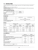
Страница 40: ...ypass Input Injector Bypass Marking Size Marking Marking Size Marking Wok burner 15 2 MJh 1 internal 112 1 12mm 90 15 0 MJh 1 internal 66 0 67mm 54 external 164 1 65mm external 91 0 87mm Large burner...

Страница 41: ...39 Notes...

Страница 42: ...40 Notes...

Страница 43: ...41 Notes...

Страница 44: ...Clarence Street Royal Leamington Spa Warwickshire CV31 2AD England Tel 44 0 1926 457400 Fax 44 0 1926 450526 E mail consumers falconappliances co uk...

Отзывы: