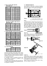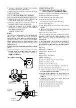
2.2 CONNECTION TO A GAS SUPPLY
The gas supply piping and connection to appliance
must be installed in accordance with the various
regulations listed on the cover of this document.
On natural gas appliances, the adjustable governor
MUST be fitted to the supply, securely fixed in a
position which will enable adjustments to be made
during commissioning.
On propane appliances, a governor must not be
fitted.
Ensure isolating isolating cock is fitted close to range
in an accessible and spillage free position.
Important: Check installation for gas tightness.
2.3 CONNECTION TO AN ELECTRICITY SUPPLY
Not applicable to these models.
2.4 CONNECTION TO A WATER SUPPLY
Not applicable to these models.
2.5 PRE-COMMISSIONING CHECK
After installation, the engineer should check that all
gas connections are gas tight and do not leak.
Check that unit is operating satisfactorily before
leaving the kitchen. Burner and gas valve
adjustments should be in line with details in
Section 1.11. If adjustment is required, then the
appliance requires to be serviced.
2.6 INSTRUCTION TO USER
After installing and commissioning appliance, please
hand User Instructions to user or purchaser and
ensure that the person(s) responsible understands
the instructions for lighting, turning off and correct use
and care of the unit.
It is important to ensure that the gas isolating cock
location is made known to the user. The procedure for
operation in an emergency must be demonstrated.
SECTION 3 - SERVICING AND
CONVERSION
Important
BEFORE ATTEMPTING ANY SERVICING,
ENSURE THAT THE ISOLATING COCK IS
T U R N E D O F F A N D C A N N O T B E
INADVERTANTLY TURNED ON.
AFTER ANY MAINTENANCE TASK, CHECK THE
APPLIANCE TO ENSURE THAT IT PERFORMS
CORRECTLY AND CARRY OUT ANY NECESSARY
ADJUSTMENTS AS DETAILED IN SECTION 1.
After carrying out any servicing or exchange of gas
carrying components -
ALWAYS CHECK FOR GAS TIGHTNESS!
3.1 CONVERSION
For conversion to NATURAL GAS, fit the correct
governor and set the burner pressure.
For conversion to PROPANE GAS, remove the
governor fromthe gas circuit.
Other considerations -
CHANGE INJECTORS (Refer to Section 1.9)
ADJUST BYPASS SCREW TO SET LOW RATES
(Refer to Section 3.8) in gas taps and any oven
thermostat.
CHANGE DATA PLATE
3.2 REMOVAL OF PANELS
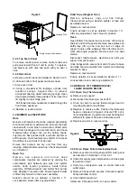
3.2.1 RH Outer Panel
Remove fixings which secure panel bottom flange to
underside of base. Slide panel back to withdraw two
pins which locate rear of vertical control panel.
Pull panel out slightly at bottomthen draw it down
to clear top flange which engages under hob edge lip.
To replace, the stainless steel outer panels are fitted
between hob and base of unit approximately 25mm to
rear of their final position. Both panels are then slid
forward into position, the RH one to engage its
locating pins into the slots in the rear of vertical
control panels and LH to align flush with front frame.
The fixings (2 off) engage the bottomflange of the
side panels up through holes in the edge of the base
panel (see Figure 5).
3.2.2 Bottom Front Panel
Lift to unhook and lower. Undo lower RH hinge pin
and remove panel. Replace in reverse order.
3.2.3 Vertical Control Panel
Pull off control knobs. Remove fixings which secure
panel bottomflange to base plate. Withdraw panel
outward slightly at bottomto clear control spindles
and pull it down to free top locating flange. Replace in
reverse order.

