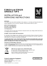
E350/35 GRIDDLE PLATE - WIRING DIAGRAM (Drawing No. BW32471/B)
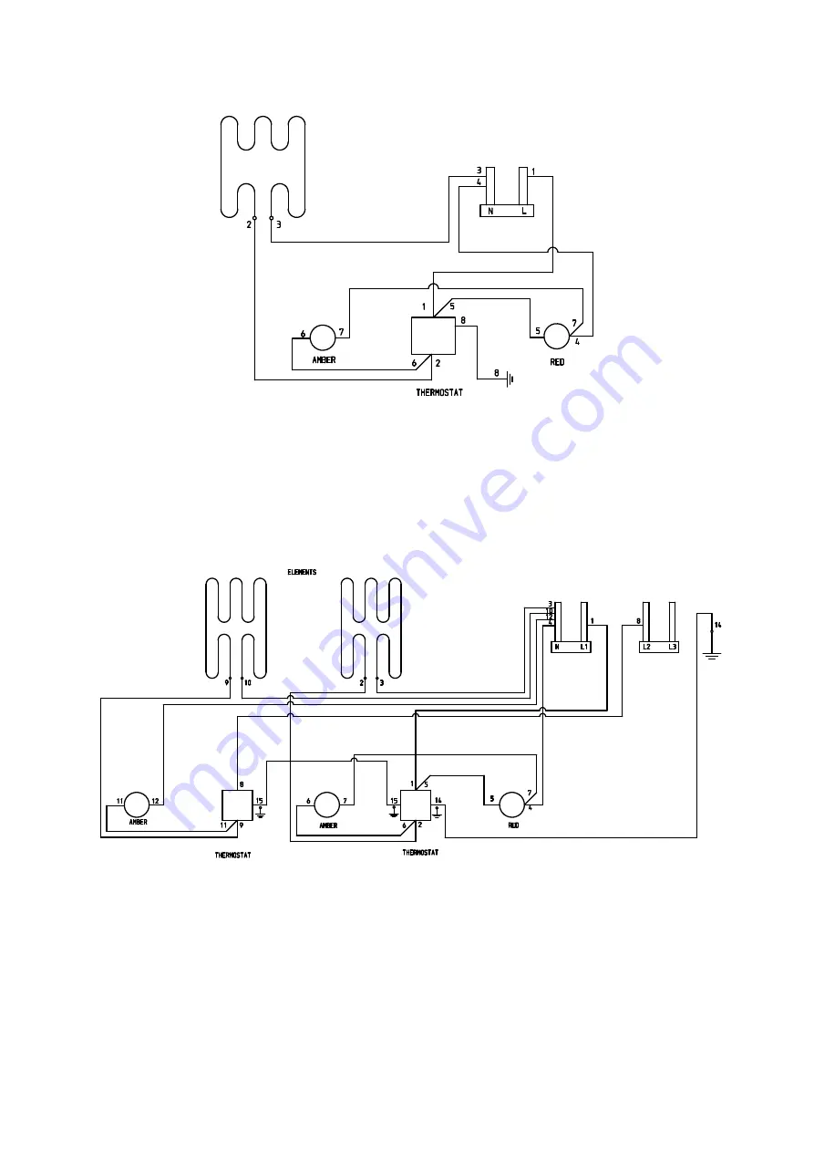
E350/34 GRIDDLE PLATE - WIRING DIAGRAM (Drawing No. AW32470/B)
Страница 1: ...monstration of the operation and cleaning of the appliance IT IS MOST IMPORTANT THAT THESE INSTRUCTIONS BE CONSULTED BEFORE INSTALLING AND COMMISSIONING THIS APPLIANCE FAILURE TO COMPLY WITH THE SPECI...
Страница 2: ...Gas water and electrical supply external to unit Light bulbs Re installing vacuum in kettle jackets Replacement of grill burner ceramics when damage has been clearly caused by misuse Where an engineer...
Страница 3: ...n access to terminals proceed as follows Remove fat drawer s Remove two screws in upper flange of control panel Allow panel to drop down slightly to release lower fixings The arms should be swung out...
Страница 4: ...at from panel Feed capillary tube and phial forward through rear of control compartment and remove assembly Replace in reverse order taking care to fit insulating sleeving over capillary before fittin...
Страница 5: ...E350 35 GRIDDLE PLATE WIRING DIAGRAM Drawing No BW32471 B E350 34 GRIDDLE PLATE WIRING DIAGRAM Drawing No AW32470 B...