background image

THE ARDMORE WOOD BURNER NON BOILER STOVE

INSTALLATION INSTRUCTIONS

GENERAL

When installing and maintaining your  Stove respect
basic standards of fire safety.  Read these instruc-
tions carefully before commencing the installation.
All relevant European and National Standards must
be complied with when installing this appliance.
Failure to do so may result in damage to persons
and property.  Consult your local Municipal office
and your insurance representative to determine
what regulations are in force.  Save these instruc-
tions for future reference.

Special care must be taken when installing the stove
such that Health & Safety requirements are met.

Handling

Adequate facilities must be available for loading,
unloading and site handling.  

Fire Cement

Some types of fire cement are caustic and should
not be allowed to come into contact with the skin.  In
case of contact with the skin wash immediately with
plenty of water.

Asbestos

This stove contains no asbestos.  If there is a possi-
bility of disturbing any asbestos in the course of
installation then please seek specialist guidance and
use appropriate protective equipment.

Metal Parts

When installing or servicing this stove care should
be taken to avoid the possibility of personal injury.

“IMPORTANT WARNING”

This stove must not be installed into a chimney that
serves any other heating appliance.

2

The complete installation must be done in 
accordance with current Standards and Local
Codes.  It should be noted that the requirements
and these publications may be superseded during
the life of this manual.

FLUES

Flues should be vertical wherever possible and
where a bend is necessary, it should not make an
angle of more than 45

o

with the vertical.  Horizontal

flue runs should be avoided except in the case of a
back outlet from the appliance, when the length of
the horizontal section should not exceed 150mm.

In order to minimise flue resistance and to make
sweeping easier it is recommended to use 2 x 45

o

bends rather than a 90

o

bend.

The flue termination point must be located to min-
imise any wind effects.  Wind effects of suction,
pressure zones and turbulence can be created by
the roof and adjacent objects.  Wind effects can also
be created by natural land contours.

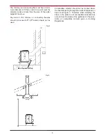
To minimise the wind effects, the flue termination
point should be located a minimum of 400mm mea-
sured vertically from the roof or any other object that
may cause an obstruction and 8 meters measured
horizontally.  Where this termination point does not
suffice it may be necessary to extend the flue pipe.
(See Fig.1)

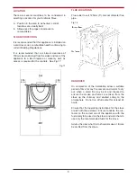
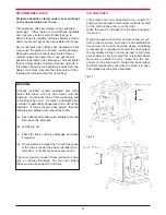
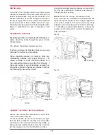
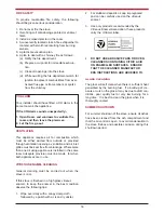
Fig.1

Содержание Ardmore

Страница 1: ...nfirm persons should be supervised at all times and should not be allowed to touch the hot working surfaces while in use or until the appliance has thoroughly cooled When using the stove in situations...

Страница 2: ...ted Air 8 11 CO Alarm 8 12 Location 9 13 Floor Protection 9 14 Flue Locations 9 15 Handover 9 16 Technical Data 10 17 Specification 10 18 Installation Check list 11 19 Operating Instructions 12 20 Imp...

Страница 3: ...tove care should be taken to avoid the possibility of personal injury IMPORTANT WARNING This stove must not be installed into a chimney that serves any other heating appliance 2 The complete installat...

Страница 4: ...3 Fig 4 FLUE EXIT TOP REAR The stove is designed to allow the chimney be cleaned through the stove A means must be provid ed to clean the chimney such as a soot box access door in the flue for cleani...

Страница 5: ...ill result in poor performance In adverse weather conditions down drafts may be experienced causing smoke or fumes to spill into the room If this occurs shut the appliance down by closing the air cont...

Страница 6: ...pipe should not exceed 45o 90o bends should not be used Fig 9 Combustible material should not be located where the heat dissipating through the walls of fireplaces or flues could ignite it Therefore w...

Страница 7: ...Fig 10 Fig 11 Fig 12 Fig 13 Fig 14 Fig 15 6 CLEARANCE TO COMBUSTIBLES CORNER INSTALLATION ALCOVE INSTALLATION FIREPLACE INSTALLATION FLUE CLEARANCES MINIMUM COMBUSTIBLE ALCOVE MANTLE CLEARANCE...

Страница 8: ...ining a shower Air vents traversing cavity walls should include a continuous duct across the cavity The duct should be installed in such a manner as not to impair the weather resistance of the cavity...

Страница 9: ...the air vent from opposite poles North South East West of the dwelling and tee off for the air supply to the stove This should negate the effect of suction and pressure zones See Fig 16 Fig 16 Note W...

Страница 10: ...controls See Fig 17 FLUE LOCATIONS Flue outlet to suit 125mm 5 internal diameter flue pipe Fig 18 9 Fig 17 HANDOVER On completion of the installation allow a suitable period of time for any fire cemen...

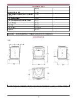
Страница 11: ...Flow 6 5 g s Flue Gas Temperature at Nominal Output 333oC Gross Weight 150kgs Flue Outlet 125mm Flue Draught 12 Pascals Log Size 340mm WARNING DO NOT OBSTRUCT PRIMARY AIR SUPPLY TO THE STOVE SPECIFICA...

Страница 12: ...chimney serving this appliance should not serve any other appliance 6 Access should be provided to the chimney serving the appliance to allow for cleaning Location 7 Clearance to combustible material...

Страница 13: ...g period of time after use Children aged or infirm persons should be supervised at all times and should not be allowed to touch the hot working surfaces while in use or until the appliance has thoroug...

Страница 14: ...at to give the required heat output 10 To shut the fire down do not add fuel make sure that the firedoor is properly closed and that the primary and secondary air controls are all in the closed positi...

Страница 15: ...ible prior to use Do not use fuels with a Petro coke ingredient as this may cause the grate to overheat causing damage Reduced outputs will result when fuels of lower calorific values are used Never u...

Страница 16: ...nal disposal If ashes are buried in soil or otherwise dumped they should be retained in the closed container until they are thoroughly cooled See Fig 23 Fig 23 the right hand edge drop into the stove...

Страница 17: ...to clean the glass when it is thoroughly cooled SUMMER SHUTDOWN For summer shutdown of the stove ensure all ashes have been cleaned from the ash compartment and that the air control is open to avoid c...

Страница 18: ...ATING TOOL 4 BASE 5 STOVE LEG 6 FRONT 7 LEFT HAND SIDE 8 RIGHT HAND SIDE 9 FIREDOOR 10 HOB 11 HOB FILLER PIECE 12 DOOR GLASS CLIP 13 ASHPAN 14 SECONDARY AIR TUBE 15 SHELL 16 DAMPER PLATE ASSEMBLY 17 L...

Страница 19: ...Manufactured by Waterford Stanley Ltd Unit 401 403 IDA Industrial Estate Cork Road Waterford Ireland Tel 051 302300 Fax 051 302315 Rev 002 DP 140905 N00562AXX 18...

Отзывы: