GPS-RECEIVER JP7-T
VERSION 1.02
3 GPS basics principle
3.1 Signal Processing Operation
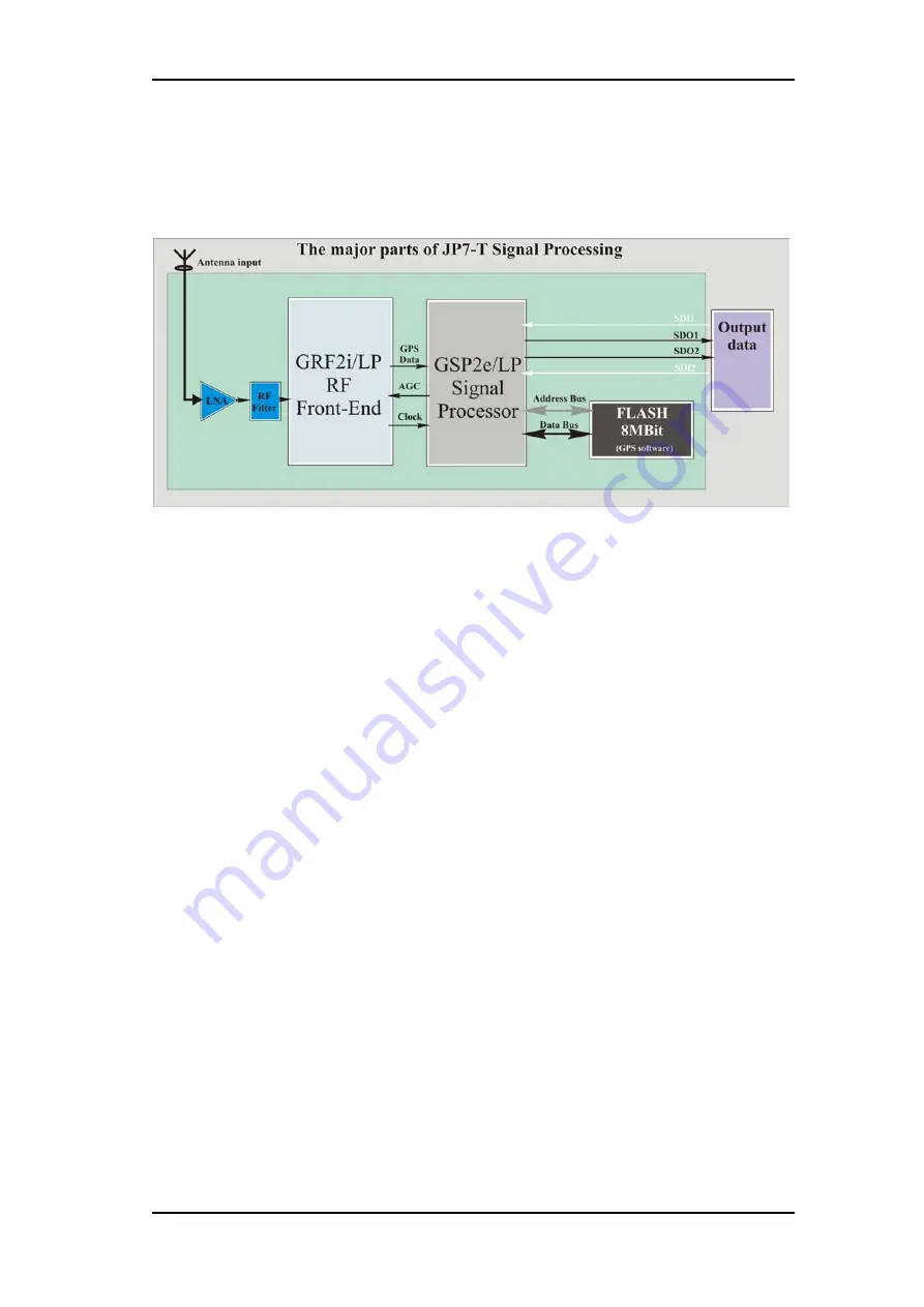
The JP7-T family is designed to use L1 Frequency (C/A Code). The module
is separated into four major parts:
RF frequency down-converter
,
digital
baseband demodulation
,
embedded ARM microprocessor
and
internal
GPS software
stored on-board (8 MBits) Flash-Memory. The RF frequency
conversion and the baseband demodulation are executed by hardware while
the embedded ARM processor computes the GPS Position, Velocity and
Time solution employing the internal GPS software.
♦
The purpose of the RF circuitry is to reinforce the very weak (-
130dBm nominal) GPS signal, filters it and down-converts it to an
Intermediate Frequency (IF) of 9.45MHz for digital processing. The
JP7-T family architecture relies on the high level of integration in the
RF part to significantly reduce part count and circuit complexity. The
IF filter is built-in as well.
♦
The digital baseband demodulator takes the quantified GPS signal and
detects the individual satellites serial data bit stream, along with the
associated pseudo range. This action consists of removing spread
spectrum and Doppler frequency components of the signal to obtain
the serial data messages.
♦
The embedded ARM processor monitors channel allocation, extracts
the raw satellite tracking data, computes the position and time solution
and sends it on a serial port for high level applications to use or
process it locally. Support functions for the microprocessor include
real-time clock and reset pulse generator circuits.
♦
The internal GPS software monitors and allocate channels, computes
the Position, Velocity and Time using the pseudo-range of the
satellites and reformat the data to be output at the serial interface or
used locally. The internal GPS software is a tasking based architecture
driven by the 100ms interrupt generated by GSP2e internal hardware.
This confidential document is the property of FALCOM GmbH and may not be copied or circulated without permission.
Page 12


