CALIBRATIONS / ADJUSTMENTS
Reverse Acting Mode Adjustment
Equipment Required for Calibration:
•
Pneumatic Supply capable of delivering up to 150 psig.
•
Current Supply capable of delivering up to 60 mA.
•
Pressure Gage capable of a digital readout up to 50 psig
with an accuracy of .1%.
•
Digital Volt Meter capable of a readout up to 60 mA with
an accuracy of .02%.
FULL RANGE OPERATION
CAUTION: Over-ranging the Zero Screw can damage unit.
Forward Acting Mode Adjustment
1.
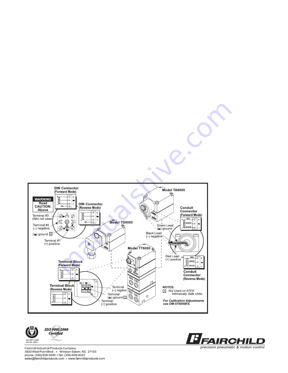
Connect the input signal to the transducer as shown
in the Installation Instructions, II-50T6000X.
•
Forward Acting Calibration-Zero
2.
Apply the minimum input signal and adjust the Zero
screw for minimum output pressure. Turn screw
clockwise to increase pressure and counterclock
wise to decrease pressure.
•
Forward Acting Calibration-Span
3.
Apply the maximum input signal and adjust the Span
screw for maximum output pressure. Turn screw
clockwise to increase pressure and counterclock
wise to decrease pressure.
4.
Repeat steps 2-3 until the desired output range is
obtained. For detailed information, see Figure 1
“TXPD6000 Calibration Configuration” on page 1.
5.
Connect the input signal to the transducer as shown
in the Installation Instructions, II-50T6000X.
•
Reverse Acting Calibration-Zero
6.
Apply the minimum input signal and adjust the Zero
screw for maximum output pressure. Turn screw
clockwise to increase pressure and counterclock
wise to decrease pressure.
•
Reverse Acting Calibration-Span
7.
Apply the maximum input signal and adjust the Span
screw for minimum output pressure. Turn screw
clockwise to decrease pressure and counterclock
wise to increase pressure.
8.
Repeat steps 6-7 until the desired output range is
obtained. For detailed information, see Figure 1
“TXPD6000 Calibration Configuration” on page 1.
SPLIT RANGE OPERATION
All units have the capability to be split ranged or set for any
output in the range as long as the Output Span is equal to
or greater than the minimum Span.
ATEX Directive - Special
Conditions for Safe Use:
The enclosure is manufactured from aluminum alloy. In rare
cases, ignition sources due to impact and friction sparks could
occur. This shall be considered when the equipment is installed in
locations that specifically require Group II, category 1G equipment.
LEGAL NOTICE:
The information set
forth in the foregoing
Operation and Mainte
nance Instructions
shall not be modified
or amended in any re
spect without prior
written consent of
Fairchild Industrial
Products Company. In
addition, the informa
tion set forth herein
shall be furnished with
each product sold in
corporating Fairchild's
unit as a component
thereof.
II-5T6000ES
Litho in USA
Rev. F 06/07


