


Drives
3.
Ref.1912
· 125 ·
DDS
HARDWARE
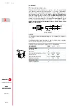
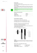
The following table shows the values for gap, tightening torque, sections
and other data of the plug-in connector for X2.
The description of the pins of this connector is:
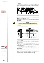
SPEED ENABLE AND DRIVE ENABLE
Normal operating mode
1
Activate the Drive Enable and Speed Enable inputs (24 V DC) in the
desired order. Before activating, the Soft Start process ( smoothly
reaching the power bus voltage ) must be over. The motor will have torque
only when Drive Enable is active and there is voltage at the power bus.
The motor speed will be controlled with a command when the Speed
Enable function is active.
2
The motor will respond to all analog command variations only while
both inputs (Drive Enable and Speed Enable) are at 24 V DC. If any of
them is deactivated, the following will happen. See the operation modes
in figure
Deactivation of the Drive Enable input
The Drive Enable input lets the current circulate through the motor stator
windings. When it is powered with 24 V DC the current is enabled and the
drive can work.
If the Drive Enable input drops to 0 V DC (no voltage), the power circuit is off
and the motor will have not torque, hence not being governed and will turn
freely until it stops by friction.
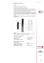
T. H3/7
Pins of aerial plug-in connector X2. Technical data.
AXD|SPD|MMC
1.XX
2.XX
3.XX
Connector data
Nr of poles
8
8
8
Gap (mm)
5
5
5
Min./max. tightening torque (N·m)
0.5/0.6
0.5/0.6
0.5/0.6
Screw thread
M3
M3
M3
Min./max. section (mm²)
0.2/2.5
0.2/2.5
0.2/2.5
Rated current In (A)
12
12
12
Connection data
Length to strip (mm)
7
7
7
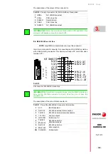
T. H3/8
Signals at the pins of connector X2 of the modular drive.
1
GND
Control signals
Reference 0 V for control signals
2
Drive Enable
Drive current enable (24 V DC)
3
Speed Enable
Drive speed enable (24 V DC)
4
Drive OK
Contact indicating module status
(it opens in case of failure). Limit 1 A at 24 V DC.
5
Drive OK
6
Chassis
Chassis connection.
7
0 V DC (IN)
Supply input
for the control
circuit
Reference 0 V
8
+24 V DC (IN)
Positive voltage input
(21
28 V DC)
x1
INFORMATION.
Activating the Drive Enable function requires to be
requested by the system in three different ways. They are: Electrical signal
at connector X2, variable BV7 (F00203), and variable DRENA of the PLC
when using the SERCOS-II or CAN interface. It could be deactivated through
any of them. Only via connector X2 is certified. See chapter
.
i
Содержание DDS Series
Страница 1: ...DRIVE DDS Hardware manual Ref 1912...
Страница 6: ...6 Ref 1912 DDS HARDWARE 6 I This page intentionally left blank...
Страница 9: ......
Страница 10: ......
Страница 11: ......
Страница 12: ......
Страница 16: ...Ref 1912 DDS HARDWARE 16...
Страница 20: ...Ref 1912 DDS HARDWARE 20...
Страница 179: ...3 Drives Ref 1912 179 DDS HARDWARE...
Страница 180: ...3 Drives Ref 1912 DDS HARDWARE 180...
Страница 200: ...4 AUXILIARY MODULES Auxiliary modules Ref 1912 DDS HARDWARE 200...
Страница 260: ...7 Cables Ref 1912 DDS HARDWARE 260...
Страница 397: ...Sales models 12 Ref 1912 397 DDS HARDWARE 12 9 Order example F H12 21 Order example...
Страница 404: ...13 Compatibility Ref 1912 DDS HARDWARE 404...
Страница 405: ......