Hardware configuration.
CNC 8070
CENTRAL
UNIT + MONITO
R (ETX PLATFORM).
5.
Ha
rd
ware function
ality.
Co
nne
ctors.
·71·
(R
EF
: 1911)
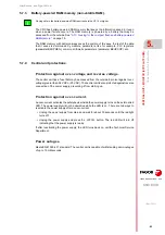
5.8.4
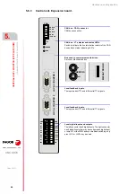
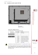
Central unit. CPU board.
CHASSIS
+24Vdc
LATCH
F5A
CHASSIS
GND
+24Vdc
(out)
Vch-
Vch+
Chassis
Vbat+
Vbat-
BAT
T
E
RY
GND
(in)
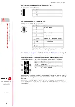
·BATTERY· connector .
Connecting the emergency battery for voltage supply and
charging it.
Ground connection.
Auxiliary 24 V DC output.
Auxiliary 24V output to supply the operator panel.
Protection fuse.
Fuse for protection against over-voltage (higher than 36 V
DC or 25 V AC).
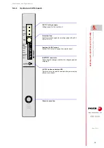
·LATCH· button and status LED.
This button may be used to reactivate the power supply
after an over-current.
24 V DC voltage supply.
Voltage supply for the central unit.
Содержание CNC 8070
Страница 1: ...Ref 1911 8070 CNC Hardware configuration...
Страница 8: ...BLANK PAGE 8...
Страница 14: ...BLANK PAGE 14...
Страница 18: ...BLANK PAGE 18...
Страница 22: ...BLANK PAGE 22...
Страница 24: ...BLANK PAGE 24...
Страница 26: ...BLANK PAGE 26...
Страница 28: ...Hardware configuration CNC 8070 1 PREVIOUS INFORMATION 28 REF 1911...
Страница 38: ...Hardware configuration CNC 8070 2 CONFIGURATION General diagram for U60 Q7 A platform 38 REF 1911...
Страница 94: ...Hardware configuration CNC 8070 6 CENTRAL UNIT MONITOR Q7 A PLATFORM 94 REF 1911 C70 15AT...
Страница 184: ...Hardware configuration CNC 8070 8 LCD 15SVGA PASSIVE MONITOR LCD15 SVGA Overall connection 184 REF 1911...
Страница 272: ...Hardware configuration CNC 8070 18 INSTALLING A SENSOR FOR GAP CONTROL LASER MODEL 272 REF 1911...
Страница 273: ...Hardware configuration CNC 8070 273 User notes REF 1911...
Страница 274: ...Hardware configuration CNC 8070 274 User notes REF 1911...
Страница 275: ...Hardware configuration CNC 8070 275 User notes REF 1911...


