Hardware configuration.
CNC 8070
12.
HORIZONTAL
KEYB 2
.0
+ TOU
CHPAD.
Enclosure
a
nd mountin
g of the modu
le.
·232·
(R
EF
: 1911)
12.4
Enclosure and mounting of the module.
12.4.1 Enclosure design.
The enclosure must meet the following requirements:
• The degree of protection of the enclosure must be IP54, according to standard IEC
60529.
• Keep the enclosure clean. If the enclosure has ventilation holes, anti-dust filters should
be installed in all of them.
• The dissipation surface of the enclosure must be enough to evacuate (by convection)
the heat generated inside.
• In the connector area, reserve a space that allows the cables to be connected, respecting
their radius of curvature.
• Respect the minimum distances recommended between the enclosure walls and the
hardware to let the air flow and improve heat dissipation.
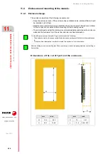
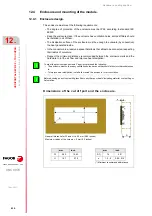
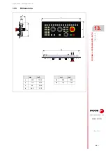
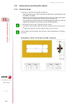
Dimensions of the cut off part and the enclosure.
To meet the previous requirements, Fagor recommends the following.
• The enclosure must not have any ventilation holes, because they could let dust or other substances
in.
• To improve heat dissipation, install a fan inside the enclosure for air circulation.
Before building an enclosure with glass fiber u another poor heat dissipating material, contact Fagor
Automation.
i
i
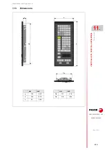
mm
inch
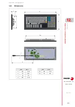
W
392
15.43
H
147
5.79
(*) Minimum recommended distance.
mm
inch
D (*)
74
2.91
e
1.5 - 4
0.06 - 0.16
H
W
e
D
R
General tolerance for W and H = ±0.5 mm (0.02 inches).
Maximum radius of the corners = 5 mm (0.2 inches).
Содержание CNC 8070
Страница 1: ...Ref 1911 8070 CNC Hardware configuration...
Страница 8: ...BLANK PAGE 8...
Страница 14: ...BLANK PAGE 14...
Страница 18: ...BLANK PAGE 18...
Страница 22: ...BLANK PAGE 22...
Страница 24: ...BLANK PAGE 24...
Страница 26: ...BLANK PAGE 26...
Страница 28: ...Hardware configuration CNC 8070 1 PREVIOUS INFORMATION 28 REF 1911...
Страница 38: ...Hardware configuration CNC 8070 2 CONFIGURATION General diagram for U60 Q7 A platform 38 REF 1911...
Страница 94: ...Hardware configuration CNC 8070 6 CENTRAL UNIT MONITOR Q7 A PLATFORM 94 REF 1911 C70 15AT...
Страница 184: ...Hardware configuration CNC 8070 8 LCD 15SVGA PASSIVE MONITOR LCD15 SVGA Overall connection 184 REF 1911...
Страница 272: ...Hardware configuration CNC 8070 18 INSTALLING A SENSOR FOR GAP CONTROL LASER MODEL 272 REF 1911...
Страница 273: ...Hardware configuration CNC 8070 273 User notes REF 1911...
Страница 274: ...Hardware configuration CNC 8070 274 User notes REF 1911...
Страница 275: ...Hardware configuration CNC 8070 275 User notes REF 1911...

