Hardware configuration.
CNC 8070
CEN
T
RAL UNIT + MONITOR (Q7-A
PLATFORM).
6.
Tech
nical
/el
ectri
cal characteri
stics of
the in
puts
a
nd outpu
ts.
·115·
(R
EF
: 1911)
6.7
Technical/electrical characteristics of the inputs and outputs.
6.7.1
Digital inputs.
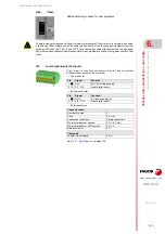
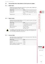
All digital inputs are galvanically isolated up to 500 V through opto-couplers. All digital inputs
meet the standard IEC61131-2 type 1 and type 3.
6.7.2
Digital outputs.
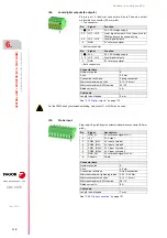
All digital outputs are galvanically isolated up to 500 V through opto-couplers. All the digital
outputs have the following characteristics:
6.7.3
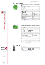
Analog outputs.
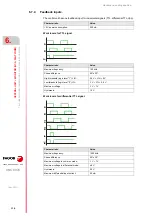
Use shielded cables connecting their meshes to the corresponding shield pin. All the analog
outputs have the following characteristics:
Characteristic.
Value.
Nominal voltage.
+24 V DC (b18 V DC and +30 V DC).
Activation level.
From +11 V DC on and between 2.1 mA and
2.6 mA.
Deactivation level.
Under +10 V DC or 1.5 mA.
Characteristic.
Value.
Nominal voltage.
+24 V DC (b18 V DC and +30 V DC).
Output voltage.
2 V less than the supply voltage.
Maximum output current.
500 mA per output.
Minimum cycle on.
Pins LO1 LO2: 25 µs.
Rest of pins: 75 µs.
For the PWM and synchronized switching, only pins LO1 or LO2 may be used. Depending on the input
receiving the PWM pulse and the cable, an external load resistor (at least 10% of rated current; if 24 V,
470
/ 2 W) improves signal quality and noise immunity.
Characteristic.
Value.
Command voltage within range.
±10 V.
Resolution.
16 bits.
Minimum impedance of the connected device.
10 k
.
Maximum cable length (unshielded).
75 mm.
Содержание CNC 8070
Страница 1: ...Ref 1911 8070 CNC Hardware configuration...
Страница 8: ...BLANK PAGE 8...
Страница 14: ...BLANK PAGE 14...
Страница 18: ...BLANK PAGE 18...
Страница 22: ...BLANK PAGE 22...
Страница 24: ...BLANK PAGE 24...
Страница 26: ...BLANK PAGE 26...
Страница 28: ...Hardware configuration CNC 8070 1 PREVIOUS INFORMATION 28 REF 1911...
Страница 38: ...Hardware configuration CNC 8070 2 CONFIGURATION General diagram for U60 Q7 A platform 38 REF 1911...
Страница 94: ...Hardware configuration CNC 8070 6 CENTRAL UNIT MONITOR Q7 A PLATFORM 94 REF 1911 C70 15AT...
Страница 184: ...Hardware configuration CNC 8070 8 LCD 15SVGA PASSIVE MONITOR LCD15 SVGA Overall connection 184 REF 1911...
Страница 272: ...Hardware configuration CNC 8070 18 INSTALLING A SENSOR FOR GAP CONTROL LASER MODEL 272 REF 1911...
Страница 273: ...Hardware configuration CNC 8070 273 User notes REF 1911...
Страница 274: ...Hardware configuration CNC 8070 274 User notes REF 1911...
Страница 275: ...Hardware configuration CNC 8070 275 User notes REF 1911...

