Installation manual
BCSD
System
PLC
4.
R
EF
. 1711
·45·
PLC program
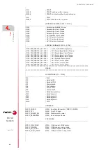
;
M_POWER_ON
; Machine with power
AND NOT M_REFERENCE
; Axis homing done
= MSG3
; Axis homing
;
;*********************************************************************
;
PLC ERRORS
;
; Management of PLC errors
;
;*********************************************************************
;
; Please write the PLC errors here
;
;*********************************************************************
;
SERVICE SCREEN
;
; Management of the Service screen.
; Service screen will be enabled while pushing the B18R562
; and CNC is in ISO+FOLLOWING ERROR, EXFOLLOWING ERROR
; or CONVERSATIONAL screens.
;
;*********************************************************************
;
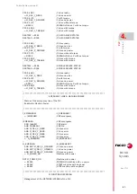
DFU B18R562
; CNC external button for Service
= CPL M300
; Commissioning OEM Screen ON
;
;*********************************************************************
;
TIME COUNTER
;
; Management of the CNC ON and Spindle running timers.
; C3 is the amount of hours that the CN is ON.
; C6 is the amount of hours that the Spindle is ON.
;
;*********************************************************************
;
; CNC ON
;------------------------------------------------------------------------------------------------
;
DFU M2017
; 1 second marker
OR DFD M2017
; 1 second marker
= CUP 1
; CNC on seconds
;
CPS C1 GE 60
; CNC on seconds
= CUP 2
; CNC on minutes
= CPR 1 0
; CNC on seconds
;
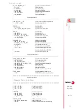
CPS C2 GE 60
; CNC on minutes
= CUP 3
; CNC on hours
= CPR 2 0
; CNC on minutes
;
;
SPINDLE RUNNING
;------------------------------------------------------------------------------------------------
;
DFU M2017
; 1 second marker
OR DFD M2017
; 1 second marker
AND DRENAS
; Spindle drive power ON
= CUP 4
; Spindle ON seconds
;
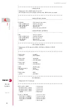
CPS C4 GE 60
; Spindle ON seconds
= CUP 5
; Spindle ON minutes
= CPR 4 0
; Spindle ON seconds
;
CPS C5 GE 60
; Spindle ON minutes
= CUP 6
; Spindle ON hours
= CPR 5 0
; Spindle ON minutes
;
;
;
Содержание BCSD
Страница 1: ...SYSTEM BCSD Installation manual Ref 1711...
Страница 4: ...4 Installation manual BCSD System REF 1711...
Страница 19: ...BCSD System REF 1711 2 19 ELECTRICAL DIAGRAM OF THE SYSTEM 2 1 3xBCSD 400 V XYZ 1xSCD 400 V S Figure 1 10...
Страница 36: ...36 Installation manual BCSD System 3 CABLES REF 1711 Encoder and Power cables...
Страница 54: ...54 Installation manual BCSD System 6 DESCRIPTION OF SYSTEM ERRORS REF 1711...
Страница 55: ...Installation manual BCSD System REF 1711 55...
Страница 56: ...56 Installation manual BCSD System REF 1711...
Страница 57: ......


