


(28/35) - DRO installation - Installation/Operation - 10iE-20iE - (Soft: 01.xx)
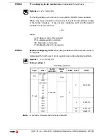
Select the desired axis and enter the number of points to be used for the axis,
up to 40. Zero means that there is no compensation table for the axis.
Where “
POS 1
” is the point number to enter and “
ERROR 1
” the amount of
error to be compensated.
Pressing [
ENTER
] displays the position value (X axis display) and the amount
of error to be compensated (Y/Z axis display).
Error to be compensated = Master's actual position - displayed position
It goes on to edit the next point.
Press this key to exit.
PAR20
It sets the configuration of the axes.
Digit
8
Turn the feedback off after 2 minutes in
"DISPLAY OFF"
mode.
7
The displays turn off if none of the axis has moved in 30 minutes. Pressing
any key or moving any of the axes turns the displays back on.
4
= 0:
The outputs are activated or deactivated when crossing the selected
level
= 1:
Deactivate the outputs when returning to position (home).
2, 1
Apply hysteresis onto the Y and X axes respectively
PAR21
Active level of the inputs.
Only the first 4 digits have a meaning.
=0:
Input active low
=1:
Input active high.
Key 1 corresponds to input 1, key 2 to input 2 and so on.
PAR23
Active level of the outputs.
Only the first 6 digits have a meaning.
=0:
Output active low
=1:
Output active high.
Key 1 corresponds to output 1, key 2 to output 2 and so on.
PAR25
Hysteresis distance
desired to avoid the flickering of the displayed position
PAR26
Distance for anticipated activation
before reaching the set position.
or
POS 1
ERROR 1
[Pos Nr]
[Error]


