


(16/35) - DRO installation - Installation/Operation - 10iE-20iE - (Soft: 01.xx)
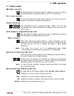
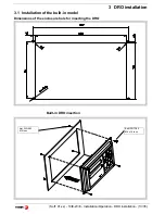
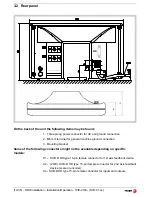
3.4 Connections
3.4.1
Connection of the feedback systems
The feedback systems (linear or rota ry encoders) are connected via SUB-D
HD type 15-pin female connectors: X1 and X2. The latter (for the 2nd axis) is
not available at the 10iE model.
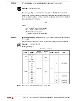
Characteristics of feedback inputs: X1 and X2:
- Power consumption: 250 mA at the +5V input.
- Admits square-wave signal (TTL). (A, B, Io)
- Maximum frequency: 250 KHz, minimum gap between flanks: 950 nsec.
- Phase shift: 90º ±20º, hysteresis: 0.25 V, Vmax: 7V,
maximum input current: 3mA
- High threshold (logic state 1) 2.4V < VIH < 5V
- Low threshold (logic state 0) 0.0V < VIL < 0.55V
Feedback connection. Connectors X1 and X2
Pin
Signal
Function
1
A
Input for feedback signals
2
/A
3
B
4
/B
5
I0
6
/I0
7
Alarm
8
/Alarm*
9
+5V
Power supply to feedback devices
10
Not connected
11
0V
Power supply to feedback devices
12, 13, 14 Not connected
15
Chassis
Shield
1


