VISY-ICI 485
Page 9/11
3
Configuration
3.1
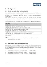
RS-485 network – bias and termination
Using the DIP switches, it is possible to bias the communication lines with a defined rest
potential and activate the terminating impedances.
By default, a bias is applied to the RS-485 network in order to improve reliability of
communication.
Under normal circumstances, communication in the RS-485 network should be
troublefree without the need for terminating impedance activation because the data rate
is relatively low.
The following table shows the possible functions depending on DIP switch configuration:
DIP switch
Function
1
2
3
4
OFF OFF OFF OFF no termination and no bias
ON OFF OFF OFF with series termination 120
Ω
/ 100 nF
ON OFF OFF ON with termination resistance 120
Ω
OFF
ON
ON
OFF
with bias (factory default)
ON ON ON OFF with series termination 120
Ω
/ 100 nF and bias
ON ON ON ON with termination resistance 120
Ω
and bias
Table 3: DIP switch
All switch positions not shown in the table are unauthorised and will
result in communication faults.
3.2
Reference to more detailed instructions
As is customary for the VISY-X System, all VISY-Input 8 / VISY-Output 4 components to
be connected need to be configured using the VISY-Setup configuration software. You
will find detailed information of the components and their configuration in the following
instruction manuals:
•
Technical Documentation VISY-Setup 4 (English) – Art. No. 207158
•
Technical Documentation VISY-Input 8 (English)
– Art. No. 207166
•
Technical Documentation VISY-Output 4 (English) – Art. No. 207131
Содержание VISY-ICI 485
Страница 2: ...Page 2 11 VISY ICI 485...
Страница 11: ......


