background image


VISY-ICI 485 

Page 7/11 


2.5


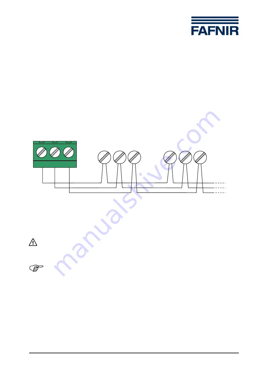
Connecting VISY-Input 8 / VISY-Output 4 

The VISY-ICI 485 supports the simultaneous operation of up to eight VISY-Input 8 and 

eight VISY-Output 4 components. The components are connected to terminal  A, B and 
GND of the 3-pole screw terminal (galvanically isolated interface). An RS-485 network is 

formed when the components are operated in conjunction with the VI-... interface card 

(also connected to the VISY-ICI 485). The optimum configuration for the RS-485 network 

is a linear topology  (daisy chaining of all network subscribers). Ring or star topologies 

should be avoided.  
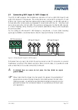
For the wiring of VISY-Input 8 / VISY-Output 4 components, a 3-core cable  including 

signal ground (GND) is recommended in order to improve immunity to interference. 

Figure 3: Connecting VISY-Input 8 / VISY-Output 4 

If shielded lines are used, the shield should be placed on the PE connection to prevent 

interference coupling. If the shield cannot be fitted on both sides, it is possible to work 

with a shield fitted to one side in the VISY-Command. 


If shielded lines are used, do not place the line shield on signal 

ground (GND). 


Please note that the longer the line length, the greater the probability of 

equipotential currents flowing through a line shield earthed on both sides. 

Where necessary, an additional equipotential bonding conductor must be 

provided between the connected devices in accordance with local rules 

and regulations. 

GND       A           B


GND         A            B


GND         A            B


VISY-ICI screw terminal


VISY-Input 8/ Output 4


VISY-Input 8/ Output 4


Содержание VISY-ICI 485

Страница 1: ...2016 09 Revision 1 Article No 207150 FAFNIR GmbH Schnackenburgallee 149 c 22525 Hamburg Germany Tel 49 40 398207 0 Fax 49 40 390 6339 VISY ICI 485 Communications adapter for connecting VISY Input 8 an...

Страница 2: ...Page 2 11 VISY ICI 485...

Страница 3: ...7 2 6 Power supply LED 8 2 7 Communication LEDs 8 3 Configuration 9 3 1 RS 485 network bias and termination 9 3 2 Reference to more detailed instructions 9 4 Technical data 10 5 List of figures 10 6 L...

Страница 4: ...CI 485 communications adapter The VISY ICI 485 is designed for operation only with the VI interface card Modifications to the VISY ICI 485 are prohibited without the prior consent of the manufacturer...

Страница 5: ...Then press the other side of the module carrier onto the rail until this side snaps into place and the module carrier is firmly locked Figure 1 Assembly The VISY ICI 485 can be used only in conjunctio...

Страница 6: ...ged as follows Figure 2 Connections LEDs and DIP switch 2 4 Connection to the VI interface card Connect the VISY ICI 485 to the VI interface card using the 6 pole ribbon cable supplied see Fig 1 This...

Страница 7: ...re cable including signal ground GND is recommended in order to improve immunity to interference Figure 3 Connecting VISY Input 8 VISY Output 4 If shielded lines are used the shield should be placed o...

Страница 8: ...green Meaning on VISY ICI 485 supplied with power off VISY ICI 485 not supplied with power Table 1 Power supply LED 2 7 Communication LEDs The two communication LEDs light up red whenever data are be...

Страница 9: ...FF OFF OFF with series termination 120 100 nF ON OFF OFF ON with termination resistance 120 OFF ON ON OFF with bias factory default ON ON ON OFF with series termination 120 100 nF and bias ON ON ON ON...

Страница 10: ...or connecting VISY Input 8 VISY Output 4 Operation indicator green LED Communication indicator red LEDs one for transmit one for receive Housing module carrier for mounting on DIN rails Dimensions h 7...

Страница 11: ......

Страница 12: ...FAFNIR GmbH Schnackenburgallee 149 c 22525 Hamburg Germany Tel 49 40 39 82 07 0 Fax 49 40 390 63 39 E mail info fafnir com Web www fafnir com...

Отзывы: