5
PIC. 6
30 cm
55 cm
15 cm
1,0 m
PIC. 7
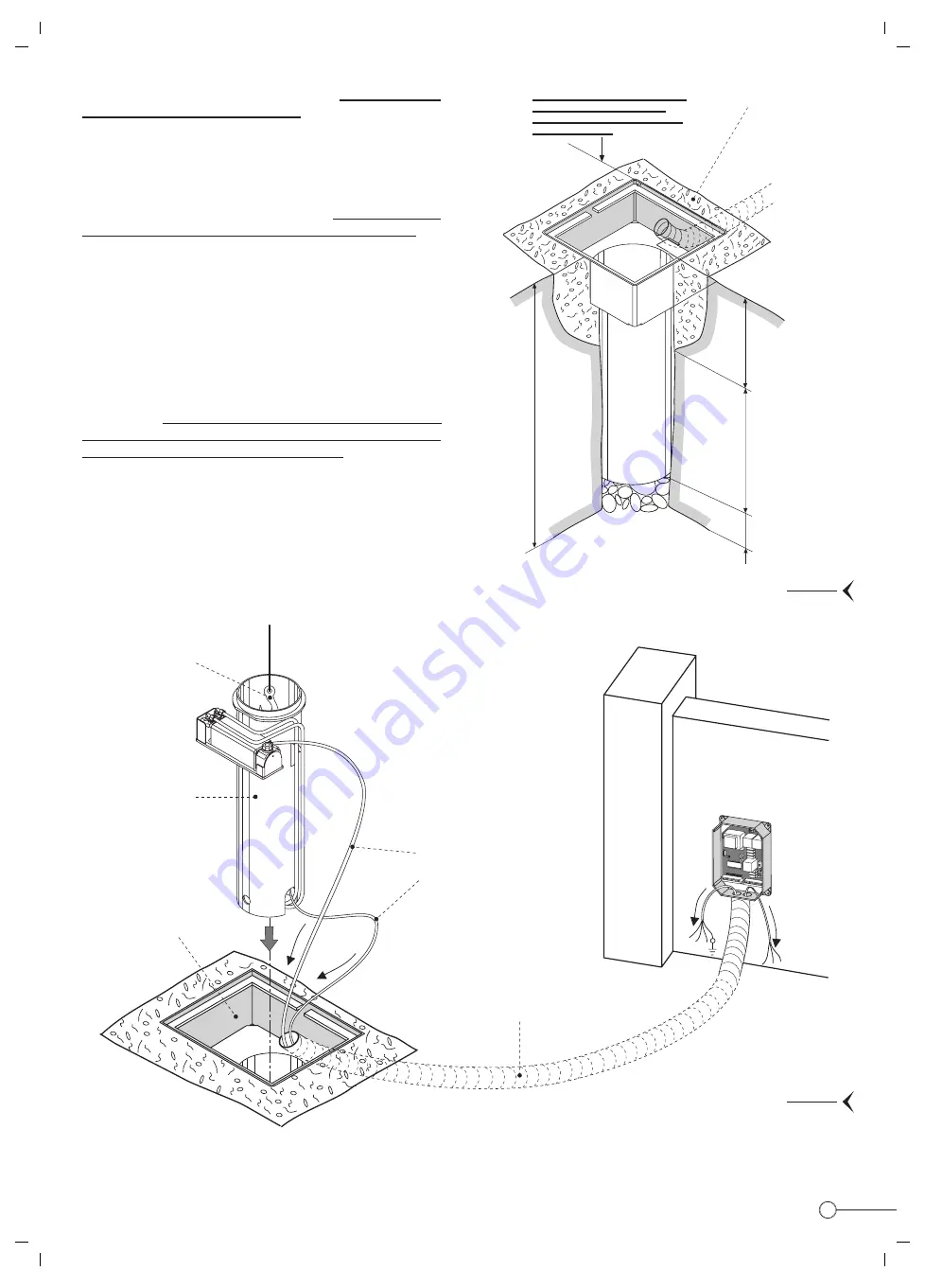
- Once located the enclosure into the pit, it is important that the
top edge is flush with the ground level.
- Fill with soil up to 55 cm and the remaining 30 cm with concrete
Pic. 6
INNER ASSEMBLY INSTALLATION
For this operation it is fundamental that the location enclosure
is very firmly set in its foundation, therefore it has to be carried
out only after you are satisfied that the concrete is well set and
the electrical duct coupled to the enclosure and laid under the
ground.
- A suitable lifting harness should be passed through the eye in
the bollard top and attached to a lifting mechanism. The assembly
should be raised from the ground and positioned directly above
the location enclosure.
- Next step. The motor and the limit switch cables should be
pulled through the duct (a rope pull-through previously inserted),
and the inner assembly gently lowered onto the location enclosure.
IMPORTANT: Pull the electric motor and limit switch cables
through the duct to the control unit. Be careful not to damage or
remove the cables from their termination Pic.7
Once satisfied that the guide tube assembly is properly fitted inside the location enclosure, fit back the bollard lid and the enclosure
cover plate (Pic. 8 on page 6).
FRONT SIDE
BACK SIDE
IMPORTANT: Once the installation
operations are completed the
enclosure top edge must be flush
with road surface
55 cm
approx.
Fill this distance
with soil
30 cm
approx.
Fill this distance
with concrete
Concrete foundation
15 cm
approx.
Shingle to clear
of standing water
Foundation
enclosure
FRONT SIDE
Electronic control unit
Elpro 10 PLUS CEI
Ø50 mm duct laid
under the ground
Electric motor and limit
switch cables, 10 m length
Guide tube
assembly
Lifting harness
Содержание VIGILO 2250
Страница 1: ...FITTING INSTRUCTIONS GB ...


