Rear Panel Operations and Connections
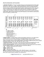
1. Speaker Terminals-
Connect your speaker wires here using good quality stranded copper
speaker wire minimum 16 – 12awg. When the amplifiers are in normal mode you can safely
connect one or two 8ohm speakers to each speaker terminal. When connecting two 8ohm
speakers wired in parallel to each terminal the speaker impedance will be 4ohms. This is the
minimum impedance of each amplifier. Never exceed a 4ohm impedance on any amplifier
output. This will damage the amplifier and void the warranty. It is possible to bridge two
amplifier channels together to double the output power. In this case the minimum impedance
will be 8ohms. Never connect more than one 8ohm speaker to each amplifier output terminal
when the amplifier is in bridge mode.
2. Bridge Switch-
The bridge switch combines two amplifier channels into one higher power
amplifier channel. The minimum impedance of a bridged amplifier channel is 8ohms.
Never connect more than one 8ohm speaker to a bridged amplifier channel. Also note that only
odd/even amplifier channel can be bridged together. The following amplifier channels can be bridged:
Bridgeable amplifier channels: 1&2, 3&4, 5&6, 7&8, 9&10, 11&12.
3. Input Level Control-
These rotary volume controls provide input level adjustments for each
amplifier channel. Use these controls to match the desired volume level in each zone.
4. Source Selection Switch-
The source selection switches provide independent source selection
for each amplifier channel. The possible selections include the following:
- IN-
(RCA jack directly above each channel)
-LEFT-
(Left BUS input)
-RIGHT-
(Right Bus input)
-AUX-
(Mono AUX Bus input)
NOTE:
It is possible to select either IN or LEFT or RIGHT and AUX. In this example
the AUX input would be used for paging and the other selected input would be used for
Music. Both inputs would be broadcast in the selected zone.
www.factorelectronics.com


