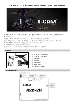
Camera # 00 (Top) = Master Camera
Camera # 01-16 = Slave C0ameras
B - Cable Lengths From Boot to Boot
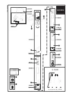
A - Wiring Diagram
1
3
2
4
R=10K
6
5
7
8
1
3
2
4
6
5
7
8
1
3
2
4
6
5
7
8
1
3
2
4
6
5
7
8
1
3
2
4
6
5
7
8
3
PIN
IO2 - Input/Output/Serial Transmit (TX)
IO3 - Input/Output/Serial Receive (RX)
GND - Ground for bi-directional IO, V
EXT
, +3.3V pins
+ 3.3V - Power external circuitry up to 150mA
4
PIN
5
PIN
8
PIN
* Refer to DWG FB360_V1_34
* Refer to DWG FB360_V1_34
00
15
14
13
16
12
11
10
09
08
07
06
05
04
03
02
01
GPIO Trigger Cable
7.
2
3" effective length
from boot to boot
6" effective length
from boot to boot
10K
resistor
Содержание Surround 360
Страница 1: ......
Страница 2: ......
Страница 4: ...1 Parts List...
Страница 13: ...Before You Start 2...
Страница 18: ...Camera Assembling Instructions 3...
Страница 35: ...4 Camera Info...
Страница 38: ...5 System Set Up Instructions...
Страница 46: ...6 Capturing Rendering Instructions...
Страница 56: ...Pro Tips 7...
Страница 57: ...Level Camera for Level Horizon Line Remove top shell first 1 7...
Страница 58: ...Avoid Close Objects 2 7 5 0 min 5 0 m i n 5 0 m i n 5 0 min recommendation only...
Страница 59: ...Be Aware of Camera Height for Better VR Experience 3 7 4 10 min 6 2 max recommendation only...
Страница 63: ...Camera Specifications 8...
Страница 67: ......