


PREPARE THE WALL
1.
Disconnect and move freestanding range from cabinet
opening to provide easier access for installation. Put a thick,
protective covering over cooktop, set-in range or countertop to
protect from damage or dirt.
2.
Determine and clearly mark with a pencil the center line
on the wall where the rangehood will be installed.
3.
The Pro Magnum attaches to the wall by mounting screws
indicated in FIGURE 5. For the 30" and 36" models, there are
two mounting screws. For the 48" model, there are four
mounting screws. Install the screws into the wall. The screws
should be inserted into the wall until the screw head is flush with
the wall.
WARNING: THE SCREWS PROVIDED FOR MOUNTING
THIS RANGEHOOD MUST BE INSERTED INTO SOLID
WOOD. THESE MUST NOT BE INSERTED INTO SHEET
ROCK.
Determine the proper location for each bracket and install the
brackets on the wall. MAKE SURE THAT THE SCREWS AND
BRACKETS ARE SECURELY FASTENED TO THE WALL.
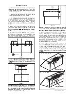
5.
Determine and make all necessary cuts in the wall for the
ductwork. The Pro Magnum vents either through the top or the
rear of the rangehood. Each rangehood is shipped from the
factory vented through the top. In order to vent to the rear, the
blower inside the rangehood must be turned to the rear. The
dimensions for the duct openings are given in FIGURE 8. The
48" model uses two 3 & 1/4" by 10" duct openings. Install all
ductwork before installing the rangehood.
6.
Determine the proper location for the Power Supply Cable
as indicated in FIGURE 8. Note that the 30"/36" versions have
the option of top or rear electrical connection while the 48"
version has only the rear option. Use a 1 & 1/4" Drill Bit to make
this hole. Run the Power Supply Cable. Use caulking to seal
around the hole. DO NOT turn on the power until installation is
complete.
Version 12/02 - Page 5
FIGURE 8
4.
The Telescopic Chimney Kit and Full Width Duct
Cover use different bracket systems to attach to the wall.
FIGURE 6 provides the position for the telescopic chimney
brackets.
48" VERSION
30" AND 36" VERSIONS
FIGURE 7
FIGURE 5
FIGURE 6
FIGURE 7 provides the dimensions for the Full Width Duct
Cover brackets. The Full Width Duct Cover also attaches to
the top of the rangehood with screws provided. The Full Width
Duct Cover must be attached to the top of the rangehood before
mounting the rangehood to the wall.
Electrical Opening
Electrical Opening
If a backsplash is to be used with this rangehood, it must be
installed before the rangehood. Installation instructions for
the backsplash are supplied in its box. The height of the
backsplash will determine the bottom edge of the canopy.


