10
6
7
8
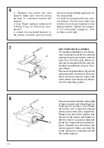
● Reattach the control box and
support. Make sure that the wiring
harness is concealed behind the
support.
● Use Power Cable provided with
3-Prong Plug for Electrical Con-
nection.
● Attach the backdraft damper to
the proper exhaust opening using
two silver screws
(12e)
supplied with
the rangehood.
● Attach the rangehood to the cabi
-
net bottom. The four key holes slip
onto the four screws mounted to the
cabinet bottom. Tighten the screws.
● Turn the power supply on. Turn
on blower and light.
DUCTLESS INSTALLATIONS
For ductless installations, the blower
must be positioned with the exhaust
pointing forward (so that the exhaust
exits from the front grill) before at-
taching the rangehood to the cabinet.
Ductless installations require Char-
coal Filters.
Remove both grease filters, the central
support and the control box. Remove
the two thumb screws on either side
of the blower and remove the blower
from the mounting guides.
Remove the two black filter holders
(A)
in figure on each end of the blower by
removing the 3 screws. Then Rotate
the blower 180° so that the exhaust
points out the front of the rangehood.
Replace the black filter holders and
the two thumb screws and tighten so
that the blower is securely fastened
inside the rangehood as indicated in
figure. Reattach the control box and
central support. Make sure that the
wiring harness is concealed behind
the central support.
A
A
Содержание AGIO24PR300-B
Страница 5: ...5 RANGEHOOD DIMENSIONS 1 12 1 3 8 1 7 8 1 1 2 2 5 8 23 5 8 29 7 8 1 2 7 1 2 6 8 1 2 47 Min 24 Min 30...
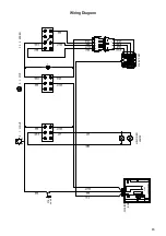
Страница 15: ...15 Wiring Diagram...
Страница 20: ...20 DIMENSIONS DE LA HOTTE 1 12 1 3 8 1 7 8 1 1 2 2 5 8 23 5 8 29 7 8 1 2 7 1 2 6 8 1 2 47 Min 24 Min 30...
Страница 30: ...30 Sch ma de c blage...
Страница 32: ...991 0492 032_05 190208 D00003397_04...


