


E721
16
532014 - Rev.E
ENGLISH
7.4 MASTER / SLAVE CONFIGURATIONS
(1)
(2)
BUS
2 EASY
(1)
(2)
BUS
2 EASY
Should you need to build a system with opposing leaves that must be activated simultaneously
for opening and closing the gate, you must connect and configure two E721 devices in Master/Slave mode.
The MASTER equipment (parameter
C t
of the first programming level configured as
M A
) must have all the necessary
connections for correct operation of the system (photocells, safety switches, radio, opening pulses, flashing light)
while the SLAVE equipment (parameter
C t
of the first programming level configured as
S L
), must not be wired with
terminal board J13, as all the inputs present are completely ignored. The two devices will communicate with each
other through BUS-2EASY using two-pole
POLARISED
wiring on the J12 terminal board.
The MASTER device will completely control the SLAVE device through BUS-2EASY and will manage all the movements
and time of both leaves.
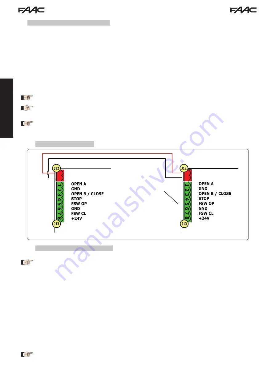
7.4.1 MASTER / SLAVE WIRING
7.4.2 MASTER/SLAVE SETUP PROCEDURE
Avoid any type of connection and wiring to terminal board J13 of the SLAVE unit.
The BUS connection between the two boards must be POLARISED following the sequence of the
poles of the J12 terminal board (POLE (1) - POLE (2)) - (see Fig. 19).
When a unit is configured as a SLAVE, this will force the values of some programming parameters
no longer displayed in the menu (
LO-PA-Pb-Ph-Op
). By placing the board in MASTER mode
again, the previously forced values are stored in the program.
E721 MASTER
E721 SLAVE
Do not connect
anything to this
terminal board
The SETUP request signalled by the flashing
S0
on the display can occur both on the MASTER unit
and on the SLAVE unit. In the latter case, the MASTER unit will display an error
91
. In any case, the
SETUP procedure can only be started from the MASTER unit.
To SETUP a MASTER/SLAVE system, follow the steps below:
1. Release both leaves, place them in the middle of travel and lock again (see procedure no.1 Par. 7.5 SETUP)
2. Keep pressed the SETUP button on the MASTER board until the MASTER gate begins to move.
3. At this point the MASTER gate will perform a complete SETUP procedure (see Par. 7.5 SETUP)
4. Once you have correctly completed the SETUP of the MASTER board, the complete SETUP procedure of the SLAVE
board begins (see Par. 7.5 SETUP).
5. Once this procedure has also been completed the MASTER checks the position of the SLAVE leaf and places it in
the same position (open or closed) as the MASTER leaf.
6. Procedure
completed.
In case of error or non-completion of the above-mentioned SETUP procedure, you must repeat it
completely starting from point no.1.
Fig. 19