17
ENGLISH
ENGLISH
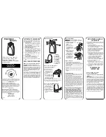
Fig.18
Fig.17
Fig.16
MINIDEC
SL/DS
PLUS
844MPS
DECODER
SL/SLP/DS
844MPS
844MPS
884 T
884 T
884 T
Fig.19
6
9
8
7
24V~ 5W max
9
8
2A max
Fig. 20
1
2
3
5.2.
DESCRIPTION
5.2.1. J1 CONNECTOR
The J1 connector is used for rapid connection of cards
MINIDEC,DECODER, RP RECEIVERS (Fig. 16, 17, 18)
Install by fitting the accessory cards so that their components
side faces the inside of the 884 T control board.
Insert and remove the cards after cutting power.
5.2.2. TERMINAL BOARD J2 (low voltage)
1 =
OPEN A (N.O.) – Total opening
This is any pulse generator with N.O. contact which, when
activated, produces a gate opening movement. In A, E
and S logics, it commands both opening and closing.
To install several Open A devices, connect N.O. contacts
in parallel.
2 =
OPEN B (N.O.) – Pedestrian Opening / Closing
This is any pulse generator with N.O. contact which, when
activated in A, E and S logics produces a gate opening
movement for pedestrians. In B and C logics, it commands
a closing movement.
To install several Open B devices, connect N.O. contacts
in parallel.
3 =
STOP command (N.C.)
This is any device (e.g. a push-button) which, by opening
a contact, stops gate movement.
To install several stop devices, connect the N.C. contacts
in series.
Ü
If Stop devices are not connected, jumper the input to
the common (terminal 5).
4 =
FSW closing safety devices contact (N.C.)
Safety devices are all devices (photocells, sensitive edges,
magnetic loops) with N.C. contact, which, if there is an
obstacle in the area they protect, operate to interrupt
gate movement. The purpose of the closing safety
devices is to protect the gate movement area during
closing.
If the safety devices are tripped during closing, gate
movement is reversed, whereas they have no effect
during opening. If engaged when the gate is open or
pausing, closing safety devices prevent its closing.
To install several safety devices, connect the N.C. contacts
in series.
Ü
If closing safety devices are not connected, jumper
this input to the common (terminal 5).
5 =
Common for commands
6 =
Common for powering accessories
7 =
Positive pole for powering 24 Vdc (+) accessories
Max load of accessories is 500 mA.
To calculate absorption values, refer to the instructions
for individual accessories.
9 =
Uscita lampada spia (Warning Light) 24 Vac
Il carico massimo della lampada spia è di 5W.
For instructions on operation of the indicator-light,
consult microswitch programming.
Ü
If you cut out jumper LK1, you obtain a free contact
between terminals 8 and 9 (see fig.19).
COMPLETE LK1
INTERRUPTED LK1
(Free contact)
11 = Limit-switch common
12 = Opening limit-switch (N.O.)
13 = Closing limit-switch (N.O.)
5.2.3. TERMINAL BOARD J3 (high voltage)
Terminal board for connecting flashing lamp (max 60W).
5.2.4. MORSETTIERA J4 (alta tensione)
Morsettiera per il collegamento del motore. Modificare i
ponticelli di collegamento motore (situati nella scatola di
derivazione sul lato destro del motore elettrico) in rapporto alla
tensione di alimentazione usata (vedi fig.14 e 15).
5.2.5. MORSETTIERA J5 (alta tensione)
Morsettiera per l'alimentazione 400V 3ph + Neutro - 50 Hz (vedi
fig.14) oppure 230V 3ph - 50 Hz (vedi fig.15).
Collegare il cavo giallo/verde di terra come in Fig.20.
5.2.6. SIGNALLING LEDs
6 LEDs are fitted on the board, indicating status of terminal
board inputs:
L
ED
LIGHTED
= contact closed
L
ED
OFF
= contact open
TAB. 4
STATUS OF LEDS
LED
LIGHTED
OFF
OPEN A
command active
command inactive
OPEN B
command active
command inactive
STOP
command inactive
command active
FSW
safety devices not engaged
safety devices engaged
FCC
closing limit-switch free
closing limit-switch engaged
FCA
opening limit-switch free
opening limit-switch engaged