14
ENGLISH
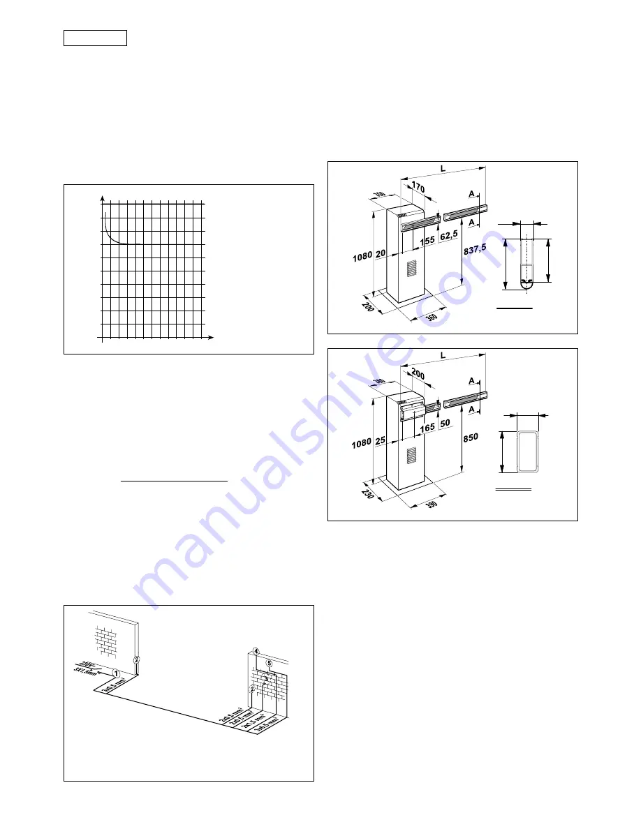
1.1. MAXIMUM DUTY CYCLE CURVE
The curve allows the maximum working time (T) to be
obtained as a function of duty cycle (F).
E.g.: The 620 rapid, 640, 642 R/40 and 642/70 operators can
work continuously with a 100% duty cycle, because they
are equipped with a cooling fan. The 620 standard and
642 std/40 models can work continuously with a 70% duty
cycle.
To ensure good operation, keep to the field of operation
lying below the curve.
Diagram of duty cycle
10
20
30
40
50
60
70
80
90
100
0
1
2
3
4
5
6
7
8
9
10
10
11
12
Percentuale
di lav. %
Tiempo (h)
% Duty cycle
% Fréquence
d'utilisation
% Benutzungs-
frequenz
% Frecuencia
de utilización
Zeit (Std.)
Temps (h)
Time (h)
Tempo (h)
620 / 642 RAP.
640 STD.
620 STD.
642 STD.
Notes:
1)
Use suitable rigid and/or flexible conduits for installation
of the electrical cables.
2)
Always route the low voltage accessory connection
cables separately from the 230 V~ power supply cables.
Use separate sheaths to avoid any interference.
a
Mod.620 / 640 / 642 barriers
b
Photocells
c
Key switch
d
Flashing light
e
Receiver
Fig. 3
4. INSTALLATING THE SYSTEM
4.1. PRELIMINARY CHECKS
For safe, correct operation of the automation system,
make sure that the following requirements are met:
•
During its movement the beam does not strike against
obstacles or overhead power cables.
•
The characteristics of the ground must ensure sufficient
support for the foundation plinth.
•
There must be no pipes or electrical cables in the area
to be dug for installing the foundation plinth.
•
If the housing is located in a vehicle transit area, it is a
good idea to provide protection against accidental
collisions.
•
Check that the housing is provided with an efficient
earth connection.
4.2. INSTALLING THE BASE PLATE
1)
Assemble the base plate, as shown in Figure. 6.
2)
Prepare a foundation plinth as shown in Fig. 7 (for soft
ground).
Values are expressed in mm.
Fig. 4
25
105,3
90
Sez. A-A
Values are expressed in mm.
Fig. 5
50
100
Sez. A-A
Important:
The curve refers to a temperature of 24°C.
Exposure to direct sunlight can result in a reduction in duty
cycle to as low as 20%.
Calculating duty cycle
The duty cycle is the percentage of effective working time
(o closing) with respect to the total cycle time
(o c pause times).
It is calculated using the following formula:
Ta + Tc
%F =
X 100
Ta + Tc + Tp + Ti
where:
Ta = opening time
Tc = closing time
Tp = pause time
Ti
= interval between a complete cycle and the next.
2. STANDARD INSTALLATION LAYOUT
3. DIMENSIONS


