7
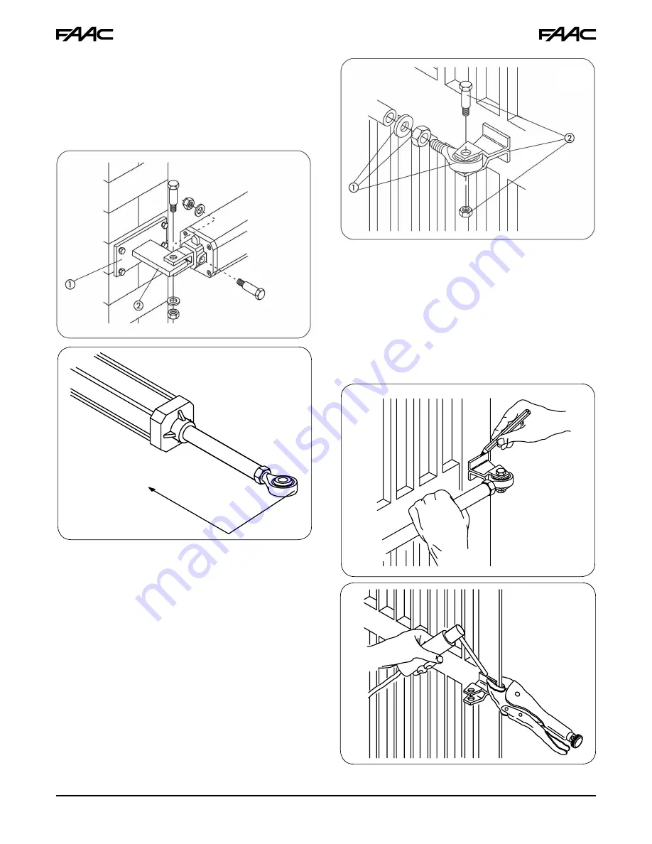
Figure 6
Figure 7
1/4 Inch
Figure 8
Figure 9
Figure 10
2.)
Secure the operator to the rear attachment with the
supplied screws (Fig. 6).
3.)
Screw, halfway down, the front attachment onto the
rod (Fig. 8, Ref.1). Tighten with the supplied nut.
4.)
Release the operator (
see Section 5
).
5.)
Fully extend the rod out to its stopping point, then push
it back approximately 1/4 inch (Fig. 7).
6.)
Relock the operator (
see Section 5.1
).
7.)
Fit the front bracket onto the rod (Fig. 8, Ref. 2)
8.)
Close the gate leaf and, while keeping the operator
perfectly horizontal, identify and mark the location of
the front bracket on the leaf (Fig. 9).
9.)
Temporarily fasten the front bracket to the leaf with two
weld spots (protect rod from welding slag).
If the gate structure does not permit the bracket
to be firmly fastened, modify the structure to
create a solid support base.
10.) Release the operator and manually check that the
gate can freely and completely open. Ensure that it
stops via the travel limit mechanical stops and that
leaf movement is good and frictionless.
11.) Temporarily release the operator from the bracket
and then permanently weld the bracket to the leaf.
Prevent welding slag from damaging the rod.
(Fig.10). If welding is not feasible, secure the front and
rear attachment plates with screws.
12.) Grease all securing pins of the attachments.
13.) Prepare the protective housing and fit it on the
operator as shown in Fig. 11. Fit the electric cable
strain relief (Fig. 12, Ref. 3).
14.) Re-lock the operator and make electrical connections
to the electronic control unit following the instructions
in the 455D section.


