

Chapter 4
Switch Hardware and Functionality
4 - 16
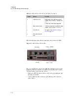
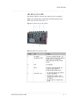
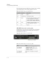
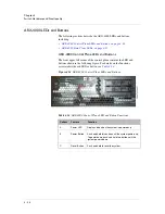
The following table describes the LED colors and patterns that occur during
various operational states, such as booting, diagnostics, and so on.
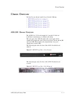
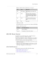
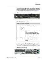
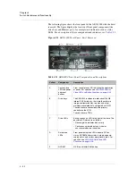
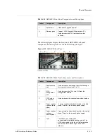
ARX-2000
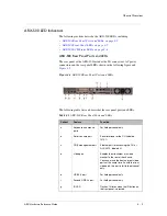
Ethernet Port Link Status LEDs
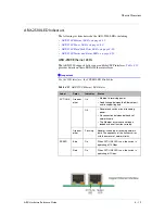
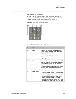
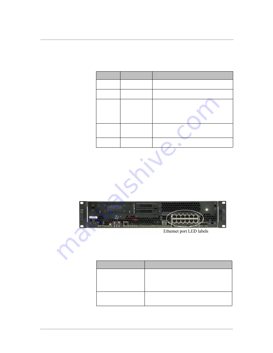
The Ethernet ports are located on the lower right front panel. The Ethernet
port LED labels are pointed out in the following figure. For details and
associated status, see
Table 4.15
.
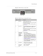
Figure 4.10
ARX-2000 Ethernet Port LED Labels
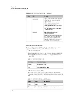
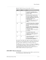
Table 4.14
ARX-2000 Alarm and Status LED States
Alarm LED
Status LED
Module State
Off
Green
Online.
Red
Green (blinking)
In the process of booting.
Off
Amber
Online Partial. At least one processor is online,
but at least one processor is not yet online.
If the offline processor does not come online in
5 minutes, this status changes to Failed Partial.
Red
Amber
Failed Partial. At least one processor is online,
but at least one processor has failed.
Off
Off
No power.
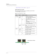
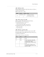
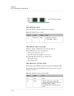
Table 4.15
ARX-2000 Ethernet Port Link Status LEDs
LED
Status
LED in upper left
connector corner
• Steady amber. Port is enabled and a link
established at 100MB.
• Steady green. Port is enabled and a link is
established at 1000MB.
LED in upper right
connector corner
Activity status. Flashing green indicates packet
traffic.
Содержание ARX-500
Страница 1: ...ARX Hardware Reference Guide MAN 0338 00...
Страница 2: ......
Страница 6: ...vi...
Страница 7: ...Table of Contents...
Страница 8: ......
Страница 12: ......
Страница 26: ...Chapter 1 Introduction 1 16...
Страница 27: ...2 ARX Overview ARX Functional Overview ARX Platform Models Managing the Switch...
Страница 28: ......
Страница 36: ...Chapter 2 ARX Overview 2 10...
Страница 37: ...3 System Specifications System Specifications System Power Requirements Cable Requirements...
Страница 38: ......
Страница 56: ......
Страница 87: ...Index...
Страница 88: ......


