background image

- 44 – 

Copyright © 2008, F5 Networks, Inc.  All rights reserved. 

Step 2 Replace rail kits 

  Replace the rails making sure to install them on the proper side and in the proper direction 

(see Fig.41).  Rails are labeled to indicate which side of the rack they belong on and which end 
is the front.  Hold the rail kit inside the rack, line up the rail kit on a rack unit boundary and 
extend the rails until the multi-pin adapter snaps into the front and back of the rack (see Fig. 
42).  


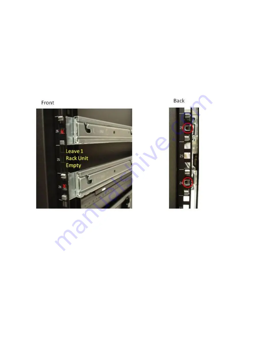
Fig. 42 


  The data plane and control plane are each two rack units tall, so rack rails should be installed 

one rack unit apart with at least one rack unit above the top rail (see Fig. 42).  This will allow 
for proper racking of the ARX 4000. Once the rails are in place, you should install the screws in 
the back of the rack rails to hold the rails into the cabinet.  Do not install the front screws, as 
the ear assembly uses these holes to secure the ARX 4000 into the rack. 

Step 3 Follow-up 

  You must contact F5 Support to ensure new part is functional 

Содержание ARX-4000

Страница 1: ...ARX 4000 D103 Parts Replacement Guide June 20 2014 Version 1 4...

Страница 2: ...loys a highly modular design that allows several key components to be replaced on a FRU basis Several of these FRU s can only be reached by removing the Front Bezel Step 1 Remove front bezel Using the...

Страница 3: ...2 Copyright 2008 F5 Networks Inc All rights reserved Installing the Bezel Step 1 Installing Bezel Push Bezel until fully seated Fig 14...

Страница 4: ...3 Copyright 2008 F5 Networks Inc All rights reserved ARX 4000 Chassis Overview Front without bezel ARX 4000...

Страница 5: ...4 Copyright 2008 F5 Networks Inc All rights reserved ARX 4000 4000 Control Plane Differences...

Страница 6: ...5 Copyright 2008 F5 Networks Inc All rights reserved ARX 4000 Chassis Overview Front without bezel...

Страница 7: ...6 Copyright 2008 F5 Networks Inc All rights reserved ARX 4000 Chassis Overview Rear...

Страница 8: ...7 Copyright 2008 F5 Networks Inc All rights reserved ARX 4000 Chassis Overview Rear...

Страница 9: ...the correct X2 module needs to be replaced There are two X2 modules 2 1 and 2 2 They are labeled as such on the bottom of the slot 2 1 is the left most and 2 2 is the right most if facing the front of...

Страница 10: ...ight 2008 F5 Networks Inc All rights reserved Installing a X2 module Step 1 Place the X2 module into the slow heat sink side up Fig 2 Step 2 Push forward on the X2 module until fully seated in the slo...

Страница 11: ...Copyright 2008 F5 Networks Inc All rights reserved Step 3 Remove the dust cover Step 4 Plug in the existing fiber optic cable Step 5 Follow up You must contact F5 Support to ensure new part is functio...

Страница 12: ...ement contact F5 Support Ensure the replacement is being performed on the backup switch and the active switch is fully functional by running the show redundancy command Ensure the switch is powered of...

Страница 13: ...12 Copyright 2008 F5 Networks Inc All rights reserved Step 3 Start to remove the battery casing by pulling on one screw Fig 5 Step 4 Pull out entire cartridge by grasping top and bottom of casing Fig...

Страница 14: ...13 Copyright 2008 F5 Networks Inc All rights reserved Installing the battery Step 5 Push battery casing into the slot Fig 7 Step 6 Turn both screws clockwise to tighten...

Страница 15: ...14 Copyright 2008 F5 Networks Inc All rights reserved Fig 8 Step 7 Turn on ARX 4000 Step 8 Install front bezel Step 9 Follow up You must contact F5 Support to ensure new part is functional...

Страница 16: ...t contact F5 Support Ensure the replacement is being performed on the backup switch and the active switch is fully functional Ensure the switch is off Removing a hard drive Step 1 Remove the front bez...

Страница 17: ...16 Copyright 2008 F5 Networks Inc All rights reserved Step 4 Pull on hard drive case to remove drive fully from slot Fig 10...

Страница 18: ...8 F5 Networks Inc All rights reserved Installing a hard drive Step 5 Place hard drive into slot Step 6 Push on the right hand side to fully seat the drive Fig 11 Step 7 Push lever forward to lock leve...

Страница 19: ...18 Copyright 2008 F5 Networks Inc All rights reserved Step 8 Install front bezel Step 9 Follow up You must contact F5 Support to ensure new part is functional...

Страница 20: ...Support Ensure the replacement is being performed on the backup switch and the active switch is fully functional Turn off the ARX 4000 prior to replacement Removing the PCIe cable Step 1 Turn off ARX...

Страница 21: ...nstalling the PCIe cable Step 1 Install new PCIe cable Push the new cable into the slot on both the control and data plane The green dot faces down Fig 16 Step 2 Turn on ARX 4000 Step 3 Follow Up You...

Страница 22: ...nt contact F5 Support This is a hot swap procedure requiring no power down of the switch and no loss of service Power Supply 1 1 is the top power supply Power Supply 1 2 is the bottom power supply Rem...

Страница 23: ...ks Inc All rights reserved Installing a Control Plane power supply Step 4 Insert new power supply into slot Fig 18 Step 5 Insert power cord into plug Step 6 Follow Up You must contact F5 Support to en...

Страница 24: ...part replacement contact F5 Support This is a hot swap procedure requiring no power down of the switch and no loss of service Power Supply 2 1 is the outer right power supply Power Supply 2 2 is the...

Страница 25: ...24 Copyright 2008 F5 Networks Inc All rights reserved Step 3 Push black lever to the right Fig 20 Step 4 Pull power supply out using handle...

Страница 26: ...25 Copyright 2008 F5 Networks Inc All rights reserved Installing a Data Plane power supply Step 5 Insert new power supply into slot Fig 21 Step 6 Insert power cord into plug...

Страница 27: ...26 Copyright 2008 F5 Networks Inc All rights reserved Step 7 Move clip to the right over the cord Fig 22 Step 8 Follow Up You must contact F5 Support to ensure new part is functional...

Страница 28: ...ift the two planes in and out of rack The system should be powered off Each network cable should be labeled with the name of the port to which it is connected The control plane is the top part and the...

Страница 29: ...28 Copyright 2008 F5 Networks Inc All rights reserved Step 4 Remove the four screws 2 per bracket holding the brackets in place Fig 23...

Страница 30: ...ht 2008 F5 Networks Inc All rights reserved Step 5 Slide out ARX 4000 just enough to remove the brackets by pulling on the handles on either side Fig 24 Step 6 Unscrew and detach bracket from the ARX...

Страница 31: ...Copyright 2008 F5 Networks Inc All rights reserved Step 7 Push the Data Plane back into the rack Step 8 Slide the Control Plane out of the rack Fig 26 Step 9 Lift up the gold levers on both rails Fig...

Страница 32: ...31 Copyright 2008 F5 Networks Inc All rights reserved Step 10 Lift the control plane off rails There are three points on each side of the server where it needs to be lifted out of the rail...

Страница 33: ...Step 12 The rail should slide back and the gold level should stop the outer shoulder nut from coming forward Step 13 Slide out data plane and slide control plane in so that the bracket can be installe...

Страница 34: ...33 Copyright 2008 F5 Networks Inc All rights reserved Fig 30...

Страница 35: ...l PCIe cable see Replacing PCIe cable Installing new PCIe cable Step 18 Plug power back into the Data and Control Planes Step 19 Plug network cables and or console cable back into Control and Data Pla...

Страница 36: ...le to lift the two planes in and out of rack The system should be powered off Each network cable should be labeled with the name of the port to which it is connected The control plane is the top part...

Страница 37: ...ht 2008 F5 Networks Inc All rights reserved Step 3 Slide out ARX 4000 just enough to remove the brackets by pulling on the handles on either side Fig 33 Step 4 Unscrew and detach bracket from the ARX...

Страница 38: ...Copyright 2008 F5 Networks Inc All rights reserved Step 5 Push the Control Plane back into the rack Step 6 Slide the Data Plane out of the rack Fig 35 Step 7 Lift up the gold levers on both rails Fig...

Страница 39: ...38 Copyright 2008 F5 Networks Inc All rights reserved Step 8 Lift the data plane off rails There are three points on each side of the server where it needs to be lifted out of the rail...

Страница 40: ...ls from above into the three slots on each rail Fig 37 Step 10 The rails should slide back and the gold level should stop the outer shoulder nut from coming forward Step 11 Slide out control plane and...

Страница 41: ...pyright 2008 F5 Networks Inc All rights reserved Step 13 Slide the ARX 4000 back into rack lifting the green lever to allow the two units to slide into the rack fully Fig 39 Step 14 Screw bracket into...

Страница 42: ...41 Copyright 2008 F5 Networks Inc All rights reserved Fig 40...

Страница 43: ...lacing PCIe cable Installing new PCIe cable Step 16 Plug power back into the Data and Control Planes Step 17 Plug network cables and or console cable back into Control and Data Planes Step 18 Power on...

Страница 44: ...epeat as necessary to remove other rails Rails are shipped setup for square punch clip nut style racks but the multi pin adapter can be reversed to work with racks that have circular punch holes see F...

Страница 45: ...adapter snaps into the front and back of the rack see Fig 42 Fig 42 The data plane and control plane are each two rack units tall so rack rails should be installed one rack unit apart with at least on...

Страница 46: ...ck to expose the screw locations for the ear assemblies Line up the ear assembly with the holes on the side of the units and install the four mounting screws see Fig 43 The handle on the ear assembly...

Страница 47: ...part replacement contact F5 Support This replacement requires two people to lift the two planes in and out of rack The system should be powered off Each network cable should be labeled with the name...

Отзывы: