CDD 12V PLUS
www.ffgroup-tools.com
English |
9
This is important and will prevent serious damage
to the battery pack. The charger is designed to fast
charge the battery pack between 0°C and 45°C. If the
battery pack, when inserted, is too cold or too hot,
the charger will not charge. The green LED and the
red LED will blink alternatively and continuously to
indicate this situation. Once the air temperature is
within tolerance, the fast charging will begin.
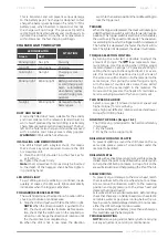
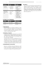
CHARGER LIGHT INDICATOR
LED INDICATOR
SITUATION
Green
Red
Blinking light
No Light
Stand by
No Light
Solid Light
Charging
Solid Light
No light
Charging is com-
plete
Blinking light Blinking light
Battery pack is too hot
or cold (charging will
begin automatically
when battery reaches
correct charging tem-
perature)
No light
Blinking light
Damaged or faulty
battery pack
DUST AND SWARF
A correctly fitted dust mask, suitable for the activity
and in accordance to the relevant standard must be
worn. Swarf produced by metal drilling is extremely
sharp. Take precautions when clearing swarf. The burr
left on the hole is also sharp and should be removed
with a suitable tool. Always wear safety goggles.
WARNING:
Drill bit will be hot after use.
INSTALLING AND REMOVING BITS
The drill is fitted with a keyless chuck, this means
that a chuck key is not required to secure the drill
or screwdriver bit.
i.
Place the drill bit shoulder into the chuck as far
as it will go.
ii.
Tighten the chuck firmly.
Note:
Short screwdriver bits need only be inserted
to the depth of the hexagon shank before tighten
-
ing chuck by hand.
LED WORK LIGHT
To aid drilling and screwdriving in confined, inade
-
quately lit spaces, the LED work light automatically
illuminates when the trigger is activated
.
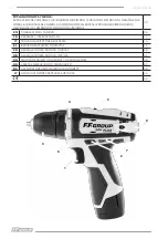
FORWARD/REVERSE SELECTOR
The switch determines the direction of rotation of the
chuck, i.e. clockwise or anticlockwise.
i.
Stop the drill and push switch
2
to the left or right.
NOTE:
When the direction switch is pushed to the
left, the chuck will rotate clockwise. Before opera
-
tion, check that the switch is set in the required po
-
sition. Do not change the direction of rotation until
the chuck comes to a complete stop.
ii.
When the drill is not in use move the direction
switch to the neutral position (the middle setting) to
lock the trigger out.
TRIGGER
When the trigger is depressed, the chuck will rotate (pro
-
vided the direction switch is set in the forward or reverse
position). This trigger switch is electronic which enables
the user to vary the speed continuously. The speed var-
ies according to how far the trigger switch is depressed.
The further it is depressed, the faster the chuck will ro
-
tate. The lighter it is depressed, the slower it will rotate.
TORQUE SELECTION CONTROL
By turning the collar
4
it is possible to adjust the
amount of torque. The
logo represents maxi-
mum torque. Use this setting when drilling wood,
metal and plastic. Settings 1-20 provide a facility for
setting the torque to the required level. For exam
-
ple, this means that repetitive driving of screws of
the same size will be driven into the material to the
same torque, thus giving the same fixing strength,
or in the case of countersunk screws, these will all
be driven to the same depth in the material. The
torque control prevents the heads of small diame-
ter screws being twisted off when correctly set.
TWO SPEED GEAR BOX
Select a low gear
1
(slower rotational speed and
higher torque) for screwdriving.
Use a high gear
2
(faster rotational speed and lower
torque) for drilling holes.
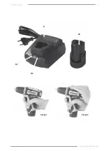
HOLDING THE DRILL
(image 1 & 2)
The drill casing is designed to be held comfortably
in two ways,
1. By the handle.
2. Or by the in-line support grip.
DRILLING WOOD AND PLASTIC
To prevent splitting around the drill holes on the re-
verse side, place a piece of scrap timber under the
material to be drilled.
DRILLING METAL
Metals such as sheet steel, aluminium and brass may be
drilled. Mark the point to be drilled with a center punch
to help the drill bit tip to locate. A drop of oil on the
area will aid cutting and help prolong the life of the bit.
SCREWDRIVING
To prevent slip or damage to the screw head, match
the screwdriver bit to the screw head size. To remove
screws, move the direction switch to the reversing
position and apply pressure to the screw head and
depress the trigger slowly).
Screwdriver bits are a consumable item. Before drilling
check that there are no hidden hazards such as electri
-
cal cables, water or gas pipes running below the sur-
face by use of a metal/voltage detector. Do not expose
either the drill or charger to rain or water.
Do not overcharge the battery (more than six hours) as
this could damage the battery cells.
TROUBLESHOOTING
NOTE:
Remove plug and/or battery before carrying
out any adjustment, servicing or maintenance.
Содержание CDD 12V PLUS
Страница 3: ...9 9 1 9 2 10 image 1 image 2 3 www ffgroup tools com CDD 12V PLUS...
Страница 22: ...CDD 12V PLUS 22 f FI RCD f f f f f f f f f f f f f f f f...
Страница 23: ...CDD 12V PLUS www ffgroup tools com 23 f f f f f f f f f f SERVICE f Y Z f f f f f f f f f f...
Страница 26: ...CDD 12V PLUS 26 ii 4 1 20 1 2 1 2 1 2 LED i ii LED LED i 2...
Страница 27: ...CDD 12V PLUS www ffgroup tools com 27 1 2 1 2 T 1 2 1 2 41 310 BL 12V 2A 41 311 CH 12V 2A...
Страница 49: ...49 www ffgroup tools com CDD 12V PLUS f f f f f f f f f f f f f f f f f f...
Страница 52: ...52 CDD 12V PLUS i ii 9 2 0A 41303 41304 10 12V 2 0Ah 41304 9 2 18 C 24 C 4 5 C 40 5 C 0 C 45 C...
Страница 53: ...53 www ffgroup tools com CDD 12V PLUS i 2 ii 4 1 20 1 2 1 2 1 2 1 2 1 2 1 2 1 2...
Страница 61: ...61 www ffgroup tools com CDD 12V PLUS...
Страница 62: ...62 CDD 12V PLUS...
Страница 63: ...63 www ffgroup tools com CDD 12V PLUS...


