


EZiSYSTEM, Functional Checks
107
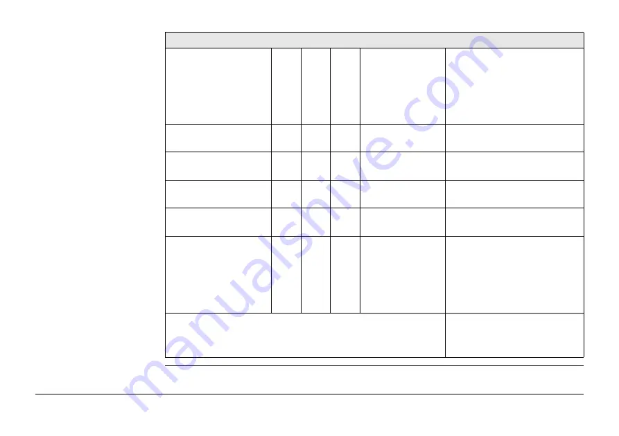
7. Batteries
Replace
Replace alkaline batteries if
pack is exhausted (no
response) or if the battery
indicator light is illuminated
or flashing after display test.
Replace all batteries!
8. Power mode
Return for repair Response width and peak
value similar to test unit.
9. Radio mode
Return for repair Response width and peak
value similar to test unit.
10. 8 kHz
Return for repair Response width and peak
value similar to test unit.
11. 33 kHz
Return for repair Response width and peak
value similar to test unit.
12. Depth Mode
(Depth Locator
only)
• 8 kHz, 33 kHz
• 512 Hz, 640Hz
(xf models)
Return for repair Gives same result as test unit
(10% accuracy).
Tested by:
Date:
Functional Test Check List