OPERATION AND SERVICE INFORMATION
Page 11
Owner’s Manual and Service Guide
Read all of Manual to become thoroughly familiar with this vehicle. Pay particular attention to all Notes, Cautions and Warnings
Place direction selector in neutral. The neutral lock
should be used to lock the direction selector in position.
This will reduce the possibility of it moving into ‘F’ (for -
ward) or ‘R’ (reverse) while being towed, causing possi-
ble damage to the rear axle.
Do not tow a single vehicle at speeds in excess of 12
mph (19 kph). Do not tow more than three vehicles at a
time. Do not exceed 5 mph (8 kph) while towing multiple
vehicles. Towing the vehicle at above recommended
speed may result in severe injury and/or damage to vehi-
cle and other property.
Tow bars are not intended for road use.
Never use ropes or chains to tow vehicle(s). Tow bars
are available from the Service Parts Department.
Tow bars are not intended for highway use. Before tow-
ing, place direction selector in neutral and engage neu-
tral lock. Do not ride on vehicle being towed. Tow bars
are designed to tow only one vehicle at a maximum
speed of 12 mph (19 kph) and up to three vehicles at a
maximum speed of 5 mph (8 kph).
NEUTRAL LOCK
To prevent the driven clutch from turning the rear wheels
during service operations and to prevent wear to the belt
while being towed, a neutral lock is located at the direc-
tion selector or the rear axle.
On Rear Axle
To operate:
Position direction selector lever between ‘F’ and ‘R’. Turn
key switch to ‘OFF’. Rotate pin on rear axle shift lever as
shown (Ref Fig. 13 on page 11). The pin will snap into a
cavity in the differential case. When in this position, the
direction selector remains locked in the neutral position.
To unlock the direction selector, pull the pin out and
rotate until the pointed portion of the pin handle fits into
the detent position in the rear axle shift lever.
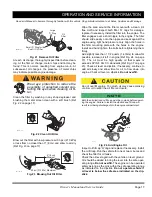
Fig. 13 Neutral Lock on Rear Axle
On Direction Selector
To operate:
Turn key switch to ‘OFF’ and lift seat. Pull out and rotate
the neutral lock pin handle so that the pointed portion of
the handle is to the side of the direction selector cam
(Ref Fig. 14 on page 11). Move direction selector towards
the area between ‘F’ and ‘R’. During that motion, the pin
will snap into the hole in the direction selector mounting
bracket preventing any movement. When in this position,
the direction selector remains locked in the neutral posi-
tion. To unlock the direction selector, pull the neutral lock
pin handle out and rotate until the pointed portion of the
handle fits into the hole in the direction.
Fig. 14 Neutral Lock on Direction Selector
Locked
Position
Unlocked
Position
Pull out and rotate 180
to lock
o
Long Tab
Short Tab
Unlocked
Locked
Pull out and rotate 180
to unlock
o
1
2
1
2
Ref Nlk 1
Unlocked
Locked
Hole in Direction
Selector Mounting
Bracket
Hole in Direction
Selector Cam
Neutral Lock
Pin Handle
1
2
Ref Nlk 2
Содержание 605584-DK
Страница 10: ...Owner s Manual and Service Guide Notes Page viii SAFETY INFORMATION ...
Страница 16: ...Owner s Manual and Service Guide Notes Page xiv SAFETY INFORMATION ...
Страница 45: ...Page 25 GENERAL SPECIFICATIONS Owner s Manual and Service Guide GENERAL SPECIFICATIONS ...
Страница 54: ...Page 34 Owner s Manual and Service Guide GENERAL SPECIFICATIONS Notes ...
Страница 55: ...Page 35 Owner s Manual and Service Guide VEHICLE WARRANTIES VEHICLE WARRANTIES ...
Страница 61: ...Appendix A 1 Owner s Manual and Service Guide LABELS AND PICTOGRAMS LABELS AND PICTOGRAMS ...
Страница 68: ......
Страница 69: ...Appendix B 1 DECLARATION OF CONFORMITY Owner s Manual and Service Guide DECLARATION OF CONFORMITY EUROPE ONLY ...
Страница 70: ...Appendix B 2 DECLARATION OF CONFORMITY Owner s Manual and Service Guide ...
Страница 71: ...Appendix B 3 DECLARATION OF CONFORMITY Owner s Manual and Service Guide ...
Страница 72: ...Appendix B 4 DECLARATION OF CONFORMITY Owner s Manual and Service Guide Notes ...
Страница 74: ......


