


ROTOR-STATOR REPLACEMENT
Rotor-Stator Replacement
x
Turn off the engine and tag out the engine.
x
Remove the two
3/4
-10 bolts that attach the rotor-stator assembly to the hopper.
x
Remove the rotor-stator cover.
x
Remove the 3/4-10 nuts and washers on the end of each threaded rod (3 places).
x
Remove the nozzle end plate welded assembly.
x
Remove the worn rotor-stator.
x
When installing the new rotor-stator make sure the rotor is aligned with the end of the auger
shaft and fully seated against it.
x
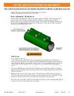
Replace the nozzle end plate welded assembly carefully aligning it with the 3 threaded rods.
Before fully seating the plate assembly against the rotor-stator rotate the rotor-stator until the
adjustment gap in the stator housing is aligned with guide bolt in the plate assembly. The guide
bolt prevents the stator housing from rotating.
NOTE: The guide bolt can be installed on
either side of the welded plate assembly depending on the configuration of the rotor-
stator from the manufacturer.
x
Reinstall the nuts on the threaded rods and tighten evenly as much as possible to apply
even pressure against the rotor-stator.
x
Evenly tighten the adjustment bolts along the stator housing.
x
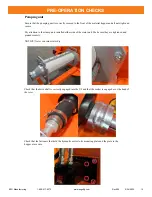
Reference the pre-operation pressure test guideline on the previous page.
x
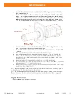
Once the hydraulics have been engaged observe the stator housing to see if it has rotated. If
any rotation has occurred, then turn off the engine. If the stator housing adjustment flange is
resting against the guide bolt, then rotate the flange away from bolt.
The guide bolt should
remain approximately in the center of the adjustment gap.
x
Evenly tighten the nuts on the threaded rods to apply more pressure against the stator
housing. Once the stator housing no longer rotates the pressure test can begin.
NOTE: It is possible to
over-tighten
the threaded rods to the point where it fle
xes
the
front rotor-stator plate and effect
s
the sealing of the O-ring.
•
Refer to the Stator
Housing Clamp Adjustment from the previous page.
•
Once 150 psi has been reached, continue to let the pump run at 50% with engine revs at
max
for 20 - 30 minutes. This will allow the stator housing to seat against the hopper and
nozzle
end plate assembly. During this time continue to monitor the pressure while checking
for and
tightening hardware that may loosen during this extended test run.
x
Refer to Shut Down Procedure on the previous page.
Guide Bolt
(
Opt. Loc.
)
Guide Bolt
NOTE
–
DO NOT
operate the driveshaft in reverse for periods longer than a few seconds. Reverse is used
to break free and to depressurize the pumping hoses in the event of a blockage.
NOTE
–
DO NOT
operate the rotor-stator without either soapy water or material in the pumping hopper.
Doing so can cause premature wear and/or damage to the rotor-stator.
Adjustment
Gap
Hopper Bolts
EZG Manufacturing 1-800-417-9272
www.ezgmfg.com
Rev000 5/24/2022 26


