background image


21 / 31 

6.3


T

RANSFER 

P

ROJECT


After a project is complete, the next step is to transfer the project to the HMI. When editing projects 
online, programming information is automatically sent to the EZ7 Series HMI unit once the project is 
saved.    When editing in an off-line mode, the project information will need to be transferred.   
More details about the transfer process is available in our 

EZ Panel Enhanced Software Manual 

and 

The basic instructions are as follows: 

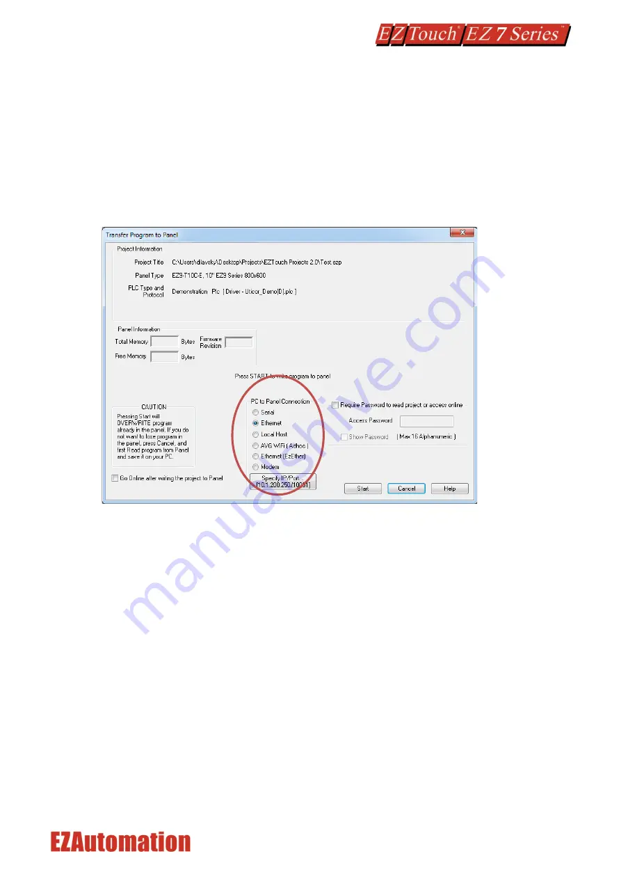
From the Project drop down menu, select 

File > Transfer to Panel

. A dialog box similar to the one 

below will appear. 


PC to Panel Connection group box lists several options. You can use Serial or Ethernet, or AVG Wifi 
(Adhoc) (this requires a special AVG Wifi module that plugs in 9 pin Serial port on panel) 

Serial: 

Use this option to use Serial port or USB type B on the panel. (When you connect USB cable, the panel 
would appear as a virtual com port). Here we describe serial port connection to the panel. 

1.


Verify the RS-232C cable (

P/N: EZ-PGMCBL

) is connected between the unit and the PC. In the 

absence of an RS-232 port on the PC, a USB to RS-232 converter may be used to connect the 
programming cable to the PC. 

2.


Select in the drop down (that appears next to Serial radio button after the option is chosen) 
COM port on the PC that is connected to the panel. And then click 

Start

. If the panel is 

connected to the right com port, project would be downloaded to the panel. 


Содержание EZ Touch EZ7 Series

Страница 1: ...Doc Ver 1 0 08 2019 EZAutomation net 1 877 774 EASY 3279 EZ Series HMI Quick Start Guide...

Страница 2: ...play Mounting dimensions 12 4 2 5 T12C 12 Display Mounting dimensions 12 4 3 Mounting Instructions 13 Ports and Wiring 16 Quickstart 17 6 1 EZTouch editor 17 6 2 Create a Project 18 6 3 Transfer Proje...

Страница 3: ...the prior written consent of AVG Automation AVG Automation retains the exclusive rights to all information included in this document Designed Built and Marketed by AVG 4140 Utica Ridge Rd Bettendorf I...

Страница 4: ...connected using a cable This construction has following benefits No large cutouts for the HMI only drill holes for the studs and a hold for cable Easily replace worn out touch screens instead of chang...

Страница 5: ...EZ7DT T12C EH EZ7 12 Inch HMI with DH Programming software and cable EZPANEL EDIT HMI Editor runs on windows 7 or higher common to all EZTouch models EZ PGMCBL Serial cable for PC to HMI connection Re...

Страница 6: ...memory Real Time Clock Yes Screen Saver Yes Battery Dimensions Installed 7 42 x 5 52 x 2 47 COMMUNICATIONS Serial Ports 2 COMPUTER port 9 Pin D Sub RS 232 port usually used for programming PLC port 1...

Страница 7: ...t all other sources of power including pneumatic and hydraulic are de energized before starting the work on a machine or process controlled by an EZ EZ7 Series HMI 2 Safety Circuits Most of the machin...

Страница 8: ...ure to humidity and liquids which may be sprayed or splashed on the equipment Dusty environments where airborne particles may accumulate on equipment causing reduction of heat dissipation and reductio...

Страница 9: ...e air space severely attenuates such interference On the other hand conducted RFI travels over conductive surfaces such as power supply wires electrical wiring of field devices and worst of all improp...

Страница 10: ...cal code requirements Once the cabinet doors stationary sub panels and swing out sub panels have been strapped to the main cabinet it is not necessary to run safety ground wires from the equipment cha...

Страница 11: ...10 31 4 2 DIMENSIONAL DRAWINGS 4 2 1 Overall Dimensions...

Страница 12: ...11 31 4 2 2 T7C 7 Display Mounting dimensions 4 2 3 T8C 8 Display Mounting dimensions...

Страница 13: ...12 31 4 2 4 T10C 10 Display Mounting dimensions 4 2 5 T12C 12 Display Mounting dimensions...

Страница 14: ...nting holes for the back unit require countersink holes Drill hole for the cable Connect display cable to the back side and mount the back side Thread the display cable through cable hole to the other...

Страница 15: ...plug in the provided HDMI cable into its connector port 3 Then use the provided screws 6 32 Philips Flat head length X 4 Screw driver Philips 2 to install the Processor Box to the inside of the Contr...

Страница 16: ...pulled through the large middle hole 2 Now insert all studs through their respective holes and use provided nuts Hex head nut size 10 32 requiring 3 8 nut driver wrench to secure the front to the cabi...

Страница 17: ...continuously Green Power connected Normal Operation Blinking Red Continuously Red Some Panel Issue has occurred Please try a power cycle if that does not fix the issue please contact Tech Support No L...

Страница 18: ...1 Please connect power to the unit and optionally connect your PLC 2 If not already done please Install EZTouch Editor on the PC See below 3 Run EZTouch Edit and start creating project 4 Transfer the...

Страница 19: ...m without having the EZ7 Series HMI unit connected through the serial port or the Ethernet connection This example will use the demonstration driver which does not require an external PLC Note The ste...

Страница 20: ...The Main Project Window will then appear showing Panel sides to the program 9 On the right side of the screen find Buttons and click on the icon The screen below will appear Enter START for Tag Name...

Страница 21: ...adjustments to the object s appearance or attributes Clicking Simulates Press will allow you to toggle between On and Off states 12 Similarly you can create an Indicator Light Object by selecting Obje...

Страница 22: ...sts several options You can use Serial or Ethernet or AVG Wifi Adhoc this requires a special AVG Wifi module that plugs in 9 pin Serial port on panel Serial Use this option to use Serial port or USB t...

Страница 23: ...ntinue and the project is now transferred 6 4 SET IP ADDRESS This section applies only to the units purchased with Ethernet capabilities Each EZ7 Series HMI unit with Ethernet comes with a factory pro...

Страница 24: ...ext click the Click to Start Designing button Now you will be in the Main Programming Window 5 Click Setup Ethernet Setup A dialog box will appear displaying the current IP parameters 6 Once the dialo...

Страница 25: ...r has multiple networks the utility will prompt you to choose one Please select the network connected to the EZ7 Series HMI unit 4 When the utility is finished scanning a list of AVG devices will popu...

Страница 26: ...l as the time and date set on the unit To change the Time Date 1 Press the Clock button 2 A new screen loads which displays a numeric keypad Enter the hour first then select Hr to change the hour Do t...

Страница 27: ...of hardware problems The EZ7 Series HMI is designed to be a very rugged controller so that just a few checks periodically will help keep it up and running The key points to be checked include Ambient...

Страница 28: ...rent firmware the available memory as well as the time and date set on the unit To test the touchpad response 1 Press the Touchpad Test button 2 A new screen will appear Press each box individually to...

Страница 29: ...To check firmware version 1 Simultaneously press the upper left corner and the bottom left corner of the screen to reach the language selection screen Select the appropriate language 2 The upper left...

Страница 30: ...splaying the Upgrade Firmware dialogue 6 Use Browse to locate the appropriate firmware version Verify Serial COM5 is selected under the PC to Panel Connection then click OK 7 On the next screen click...

Страница 31: ...the EZ7 Series HMI terminal is within the specified range Indicator LED is blinking red Outdated firmware Update firmware for unit Real Time Clock function not enabled Low Battery Remove old battery a...

Страница 32: ...uestions please call our technical support at 1 877 774 EASY Warranty Repairs If your EZ7 Series HMI is under warranty contact us at 1 877 774 EASY Out of Warranty Services If your EZ7 Series HMI is o...

Отзывы: