


VersaTools™ MDA 3 Series • Installation
VersaTools™ MDA 3 Series • Installation
VersaTools™ MDA 3 Series, cont’d
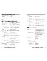
Unbalanced Output
Tip
See caution
Sleeve
Tip
See caution
Balanced Output
Tip
Ring
Sleeve (s)
Tip
Ring
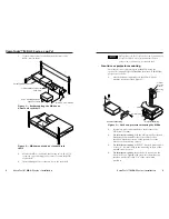
Figure 8 — Captive screw connector wiring for
audio output
CAUTION
Connect the sleeve to ground (Gnd). Connecting
the sleeve to a negative (-) terminal will damage the
audio output circuits.
7
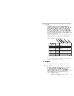
Bal(anced)/Unbal(anced) DIP switches
— For each balanced
audio output, set the associated DIP switch to the
Balanced (up) position. For each unbalanced audio
output, set the associated DIP switch to the Unbalanced
(down) position.
The balanced or unbalanced nature of the audio output is
determined by the output connector wiring, not the audio
input. Each output can be balanced or unbalanced
independently of the other two outputs.
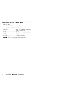
Audio on RCA connectors (MDA 3A RCA)
MDA 3A RCA
POWER
12V
.34A MAX
INPUT
OUTPUTS
1
2
3
L
R
8
9
8
9
10
MDA 3A RCA,
Rear Panel
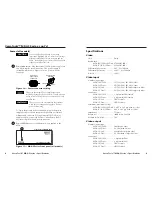
Figure 9 — MDA 3A RCA rear panel
8
Audio Input connectors
— Connect an unbalanced stereo audio
source to these L(eft) and R(ight) RCA connectors.
9
Audio Outputs (1 through 3) connectors
— Connect up to three
stereo audio devices to these L(eft) and R(ight) RCA connectors.
BAL
1 2 3
UNBAL
Audio on captive screw connectors (MDA 3AV,
MDA 3SVA, MDA 3A)
5
Audio Input connector
— Connect a balanced or unbalanced
audio input to this 3.5 mm, 5-pole captive screw connector.
Connectors are included with each MDA, but you must supply
the audio cable. See figure 6 to wire a connector for the
appropriate input type and impedance level. High impedance
is generally over 800 ohms.
Unbalanced Input
Tip
Sleeve
Tip
Sleeve
Balanced Input
Tip
Ring
Sleeve (s)
Tip
Ring
Tip
Ring
Sleeve (s)
Tip
Ring
Balanced Input
(high impedance)
(high impedance)
(600 ohms)
600 ohms
600 ohms
Figure 6 — Captive screw input connector wiring
When making connections for the MDA from existing
audio cables, see figure 7. A mono audio connector
consists of the tip and sleeve. A stereo audio connector
consists of the tip, ring and sleeve. The ring, tip, and
sleeve wires are also shown on the captive screw audio
connector diagrams, figure 6 and figure 8.
Tip (Left)
Sleeve (Gnd)
Tip (Left)
Ring (Right)
Sleeve (Gnd)
Tip
Sleeve
Unbalanced Mono
Unbalanced Stereo
Tip (Signal)
Sleeve (Gnd)
Figure 7 — Phono audio connectors
6
Audio Outputs (1 through 3) connectors
— Connect up to three
balanced or unbalanced audio devices to these 3.5 mm, 5-pole
captive screw connectors. Connect audio devices, such as an
audio amplifier or powered speakers. See figure 8 to properly
wire an output connector.
VersaTools™ MDA 3 Series • Connections and Controls
7
6
VersaTools™ MDA 3 Series • Connections and Controls


