TSC 100 • Quick Start Guide
Quick Start Guide — TSC 100, cont’d
i
TSC 100 • Table of Contents
Chapter 1 • Introduction
.......................................................... 1-1
About the TSC 100
................................................................. 1-2
Features
...................................................................................... 1-2
Chapter 2 • Installation and Operation
........................ 2-1
Rack Mounting the TSC 100
.............................................. 2-2
Connections
.............................................................................. 2-3
Rear panel connections ......................................................... 2-3
Cabling the TSC 100 ............................................................... 2-4
Operation
................................................................................... 2-4
Front panel controls and indicators ..................................... 2-5
Presets .................................................................................... 2-6
Troubleshooting
..................................................................... 2-6
Chapter 3 • Serial Control
....................................................... 3-1
Programmer’s Guide for Serial Communication
... 3-2
Device-initiated messages ..................................................... 3-2
Error responses ...................................................................... 3-2
Using the command/response table ..................................... 3-3
Symbol definitions ................................................................. 3-3
Command/response table for SIS commands ....................... 3-5
Command/response table for Special Function SIS commands
................................................................................................ 3-9
Control Software for Windows
®
.................................... 3-9
Installing the software .......................................................... 3-9
Using the software ................................................................ 3-9
Using the help system ......................................................... 3-10
Appendix A • Specifications
,
Part Numbers,
and Accessories
............................................................................. A-1
Specifications
......................................................................... A-2
Parts
............................................................................................. A-4
Included Parts ....................................................................... A-4
Accessories ............................................................................ A-4
Cables .................................................................................... A-4
Adapters ................................................................................ A-4
Table of Contents
68-623-01
Rev. C
12 04
All trademarks mentioned in this manual are the properties of their respective owners.
QS-2
Step 6
Select an input and an output standard
using the front panel
buttons or the RS-232 controller.
Step 7
The picture should now appear
. If not, ensure that all devices are
plugged in and receiving power. Check the cabling and make
adjustments as needed. Select a different input to check for a display.
Optimizing the Video
Step 1
Complete the basic setup (described above) and obtain a picture on
the output display.
Step 2
Select Aspect Ratio Preset or size and center the image through the
control program (see to page 2-6), if needed.
Step 3
Adjust top and bottom blanking, if needed, to remove edge noise.
Step 4
Using the Picture Controls button, select Brightness, then adjust the
level using the Adjust knob.
Step 5
Using the Picture Controls button, select Contrast, then adjust the
contrast using the Adjust knob.
Step 6
Using the Picture Controls button, select Color, then adjust the color
using the Adjust knob.
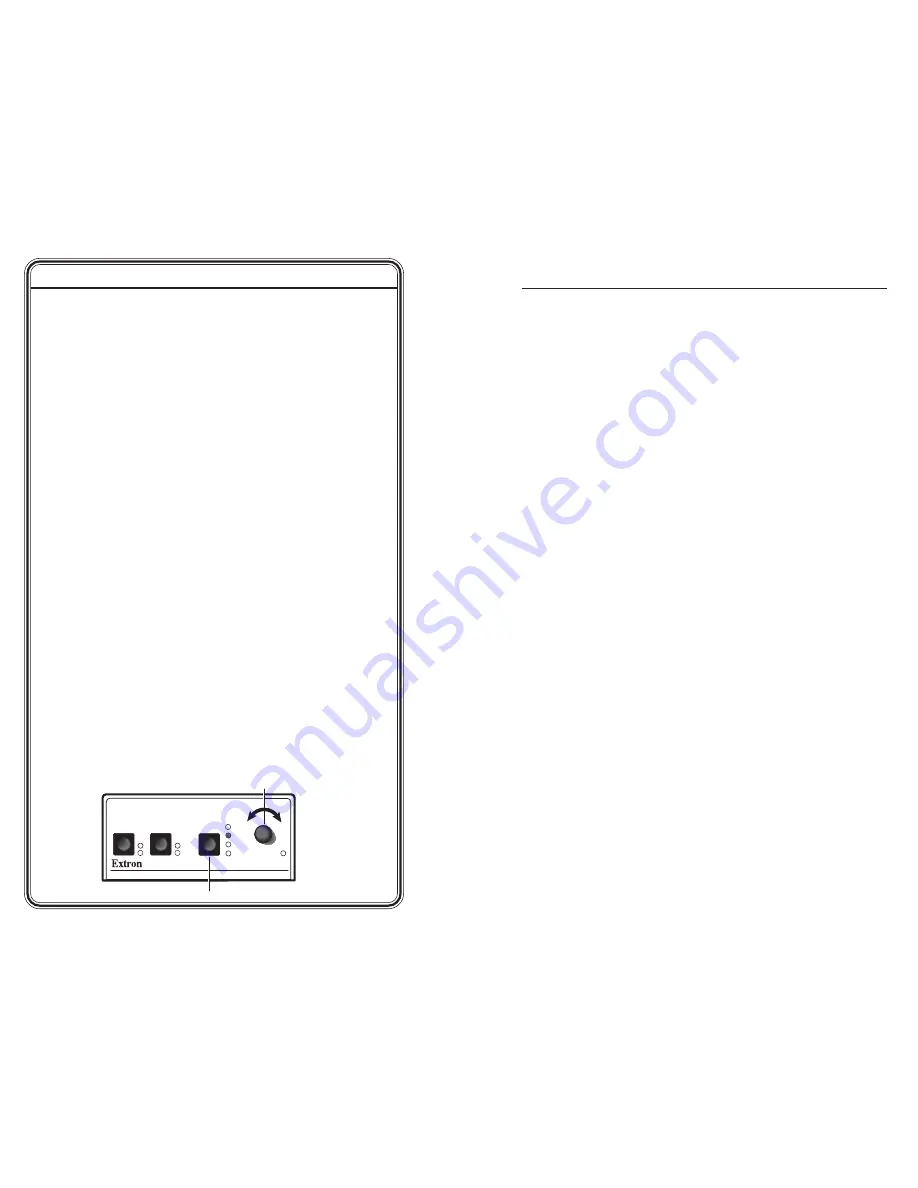
Step 7
Using the Picture Controls button, select Tint, then adjust the tint
using the Adjust knob (see example illustration below).
TSC 100
TRANSCODING STANDARDS CONVERTER
1
2
NTSC
COLOR
TINT
BRIGHT
CONTRAST
PAL
MAX
MIN/
ADJUST
INPUT
OUTPUT
PICTURE
CONTROLS
A. Press to select tint.
B. Adjust using knob.


